Heat shield device for CZ-Si single crystal furnace

A single crystal furnace, Czochralski technology, applied in the direction of single crystal growth, single crystal growth, crystal growth, etc., can solve the problem of increasing crystal heat dissipation, and achieve the effect of increasing heat dissipation, easy implementation, and saving production costs

Active Publication Date: 2012-02-15
内蒙古中环晶体材料有限公司
View PDF3 Cites 24 Cited by
  • Summary
  • Abstract
  • Description
  • Claims
  • Application Information

AI Technical Summary

Problems solved by technology

[0004] First of all, a large part of the thermal radiation reflected upward by the reflector is still absorbed by the crystal, which cannot maximize the heat dissipation of the crystal

Method used


Image

  • Heat shield device for CZ-Si single crystal furnace
  • Heat shield device for CZ-Si single crystal furnace

Examples


Embodiment 1

[0025] Using a 22-inch thermal field and a 135kg feed rate, the 8-inch solar-grade silicon single crystal is drawn. The heat shield device is arranged above the crucible along the same axis as the crucible. The argon flow rate is controlled to be 30-80slm, and the pressure in the furnace is maintained at 15-20 T. The crucible rotation speed is 6-10 rpm, and the crystal rotation speed is 8-12 rpm. According to the conventional Czochralski process, seeding, shouldering, shoulder turning, equal diameter and finishing are carried out. Among them, the position of the seeding crucible controls the guide tube to be 15-35mm away from the molten silicon liquid surface, and the pulling speed of the head is set to 75-80mm / h; as the length of the crystal increases, the pulling speed gradually decreases, and the growth speed in the middle is controlled at 65 -70mm / h. The method can increase the average growth rate of the existing 22-inch thermal field silicon single crystal from 0.9 mm / ...

Embodiment 2

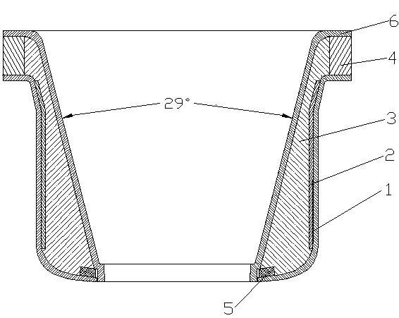
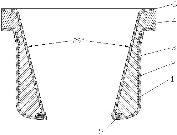
[0027] The outer cylinder is made of isostatic high-purity graphite, and its upper part is about a quarter of its height slightly conical open, and the rest of the lower part is in the shape of a hollow cylinder, with edges extending horizontally outward at the top and horizontally extending inward at the bottom edge.

[0028] Cut the 0.5mm thick cold-rolled molybdenum sheet into several small rectangles with equal width, the length of which is slightly smaller than the height of the outer cylinder. The small rectangular molybdenum sheets are close to the inner wall of the outer cylinder, and the long sides are adjacent, and there is no space between adjacent molybdenum sheets. , forming a heat reflective layer.

[0029] The carbon felt is laid along the inner surface of the heat reflection layer of the molybdenum sheet (the surface opposite to the contact surface of the molybdenum sheet and the outer cylinder), with a certain thickness to form a heat insulation layer.

[003...


PUM


Abstract

The invention relates to a heat shield device for a CZ-Si single crystal furnace and the device comprises an outer barrel, a heat protective layer, an inner barrel, a heat reflecting layer, a heat insulation pad I and a heat insulation pad II, wherein the heat reflecting layer is arranged between the outer barrel and the heat protective layer; the heat protective layer is arranged between the heat reflecting layer and the inner barrel; the heat insulation pad I is arranged between the outer barrel and the inner barrel at the upper end of the heat shield device; one end of the heat insulation pad I is tightly matched with the heat protective layer; the heat insulation pad II is arranged between the outer barrel and the inner barrel at the bottom end of the heat shield device; and one end of the heat insulation pad II is tightly matched with the heat protective layer. The heat shield device is characterized in that the action of the reflected heat radiation of a molybdenum sheet heat reflecting layer on crystals can be effectively prevented, the heat dissipation of crystals can be increased greatly and the crystal growth speed can be improved. A better heat preservation effect on the fused silica can be realized, the blow-in power consumption can be further reduced, and the production cost is saved. The heat shield device has low cost and is easy to realize.

Description

technical field [0001] The invention relates to a matching device for a Czochralski silicon single crystal furnace, in particular to a heat shield device for a Czochralski silicon single crystal furnace. Background technique [0002] At present, it takes 35-40 hours to produce an 8-inch silicon single crystal with a length of about 2 meters and a diameter of about 2 meters by the Czochralski method. The furnace has a long start-up time, high power consumption, and low production efficiency. Therefore, to solve the above problems, it is mainly to increase the crystal growth rate and shorten the crystal pulling time; fundamentally speaking, it is necessary to increase the temperature gradient of the solid-liquid interface between the crystal and the molten silicon and accelerate the release of the latent heat of crystallization, that is, to increase the temperature of the crystal. cooling rate. The high temperature furnace body and the thermal radiation of molten silicon are ...

Claims


Application Information

Patent Timeline
Patent Type & Authority Applications(China)
IPC IPC(8): C30B15/00C30B29/06
Inventor 尚伟泽谷守伟梁山王军磊高润飞高树良沈浩平
Owner 内蒙古中环晶体材料有限公司
Why Eureka
Try Eureka