Heat pipe and refrigerating system combined energy transportation method

A refrigeration system and composite technology, applied in the direction of refrigerators, refrigeration components, refrigeration and liquefaction, etc., can solve the problems of large space occupation, complex system, high energy consumption, etc., achieve small space occupation, simple structure of system devices, and energy The effect of low consumption

Inactive Publication Date: 2012-02-22
QINGDAO UNIV
View PDF6 Cites 23 Cited by
  • Summary
  • Abstract
  • Description
  • Claims
  • Application Information

AI Technical Summary

Problems solved by technology

[0003] The purpose of the present invention is to overcome the shortcomings of the prior art, in order to solve the problems of high energy consumption, difficu

Method used


Image

  • Heat pipe and refrigerating system combined energy transportation method
  • Heat pipe and refrigerating system combined energy transportation method
  • Heat pipe and refrigerating system combined energy transportation method

Examples


Embodiment 1

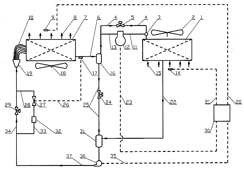
[0033] This embodiment is the workflow of the first kind of energy transportation, as attached figure 1As shown, the direction of the circulation arrow in the figure is the flow direction of the heat pipe working medium; evaporator 7, gas-liquid separator 16, condenser 1, liquid storage tank 31, solution circulation pump 36, liquid separator 19, equal length liquid equalizer Tube 10, working condition switching solenoid valves 5, 24, 29, interconnecting pipelines, temperature adjustment and control parts, etc. are organically connected to form a double-cycle controllable heat pipe system; under the working condition of the heat pipe, the working condition switching solenoid valve 5, 24, 29 are in the open state, and a relatively independent The working fluid circulates (the small cycle in the double cycle); while the gas-phase working medium enters the uniform gas distribution pipe 3 through the gas pipeline 4, the gas-phase working medium switching solenoid valve 5, and the g...

Embodiment 2

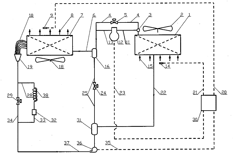
[0034] Embodiment 2: attached image 3 It is the working flow diagram of the second scheme of the present embodiment, except that the throttling parts composed of the throttle valve 27, the temperature signal line 26 for the throttle valve and the temperature sensing package 17 for the throttle valve are replaced with the throttle capillary 38, Other parts are the same as Embodiment 1. This embodiment is especially suitable for small systems, and has the advantages of simple structure and low cost; its start-up and operation process are the same as Embodiment 1.

Embodiment 3

[0035] Embodiment 3: Attach Figure 4 It is the working flow diagram of the third scheme of this embodiment, except that the gas-liquid separator 16 is replaced with the gas-liquid separation main pipe 39, the other parts are the same as in the embodiment 1, and the characteristic is that the evaporator and the gas-liquid separator are organically combined, The structure is compact; its start-up and operation process are the same as those in Embodiment 1.


PUM


Abstract

The invention belongs to the technical field of cold and heat energy transportation, and relates to a heat pipe and refrigerating system combined energy transportation method. A double circulation controlled heat pipe system and a compressed circulation refrigerating system are combined to realize energy transportation; a device system for realizing energy transportation comprises two kinds of heat exchangers, namely an evaporator and a condenser, and each kind of heat exchanger comprises one heat exchanger or two heat exchangers which are connected in parallel; the whole device system comprises the heat pipe system, the refrigerating system and five subsystems such as a condensate supplying and distributing system, a gas-liquid two-phase flowing and separating device, a gas phase conveying and distributing system, a liquid phase collecting and storing system and a temperature adjusting and controlling system; the method is used on cooling occasions of machine rooms of a communicationbase station and various power supply cabinets and control cabinets; the heat pipe system and a heat pump system work in a combined mode, and intermittent waste heat or afterheat is effectively utilized, so that an energy-saving effect is good, and energy consumption is low; and the used system device has a simple structure and small occupied space and is environment-friendly.

Description

Technical field: [0001] The invention belongs to the technical field of cold and heat energy transportation, and relates to a combined heat pipe and refrigeration system energy transportation method formed by combining a heat pipe system and a refrigeration system for heat energy transportation. Background technique: [0002] In the real life and production process, it is often necessary to transport heat from one area to another, such as communication base stations, various power supply cabinets, control cabinets, and machine rooms. The heat is transferred to the external environment; in some industrial or commercial air-conditioning systems with high internal heat source density, the heat generated by the internal heat source needs to be transferred to the external environment; The heat is transferred to the external environment, etc.; the common feature in these occasions is that in some seasons of the year, such as winter, spring and autumn, the set temperature of the he...

Claims


Application Information

Patent Timeline
IPC IPC(8): F25B23/00F25B39/00F25B49/02
Inventor 田小亮孙晖杜启行王兆俊刘瑞璟
Owner QINGDAO UNIV
Why Eureka
Try Eureka