
Method and system for preparing particle-reinforced metal-based composite material through injection molding

A particle enhancement and spray forming technology, applied in the field of enhanced particle generation and molten metal atomization, can solve the problems of large consumption of inert gas, small diameter of powder conveying pipe, affecting the uniform distribution of enhanced particles, etc., to reduce the consumption of inert gas , The particle size distribution is narrow, and the effect of improving the atomization efficiency

Inactive Publication Date: 2012-03-28
NORTHWESTERN POLYTECHNICAL UNIV
View PDF9 Cites 37 Cited by
  • Summary
  • Abstract
  • Description
  • Claims
  • Application Information

AI Technical Summary

Problems solved by technology

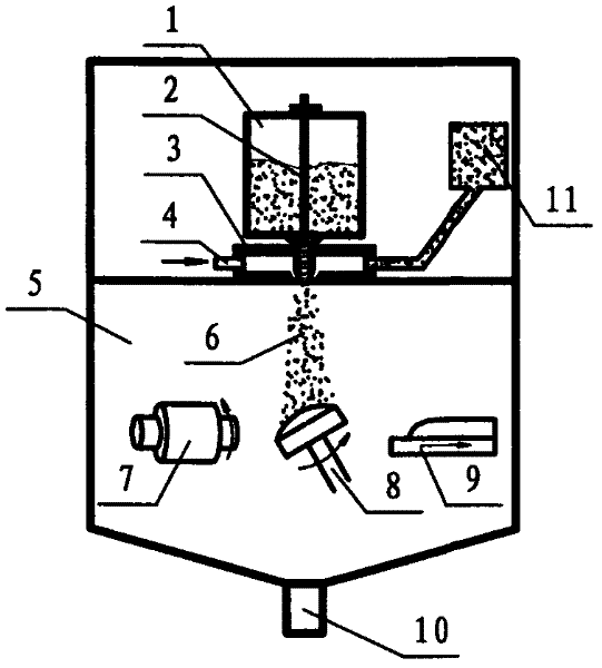
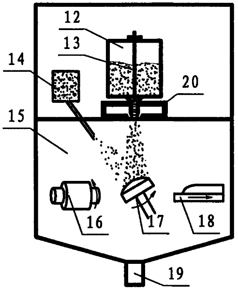
This forming method has the following disadvantages: (1) Inert gas is used to atomize the molten metal. Due to the low gas density and low momentum, the atomization efficiency is very low, a large amount of inert gas needs to be consumed, and the atomized droplet size distribution is uneven. ; (2) Ceramic particles will affect the flight trajectory of atomized droplets, making it difficult to control the shape of the deposited body
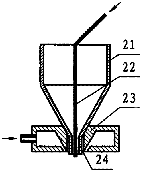
The disadvantages of this nozzle are: (1) The diameter of the powder conveying pipe is small and the length is very large, so the powder is easily blocked in the pipe, which affects the uniform distribution of the reinforcing particles inside the deposition body; (2) due to the wear of the powder conveying pipe Passing through the bottom of the tundish, the outer diameter of the guide tube 24 becomes larger, making the diameter of the air outlet of the high-pressure air chamber larger, which affects the atomization effect of the nozzle

Method used


Image

  • Method and system for preparing particle-reinforced metal-based composite material through injection molding
  • Method and system for preparing particle-reinforced metal-based composite material through injection molding
  • Method and system for preparing particle-reinforced metal-based composite material through injection molding

Examples


Embodiment approach

[0034] Step 1: Preparation of reinforced ceramic particles. Mix the raw materials according to the ratio of 50%Al+49%CuO+1%Mg (mass fraction), and carry out reaction ball milling on a vacuum ball mill for 10 hours, and Al and CuO will chemically form Al with a diameter of 15 μm 2 o 3 ceramic particles;

[0035] Step 2: the Al prepared in the first step 2 o 3 The ceramic particles are transferred to the powder bin 11 in the vacuum chamber 5;

[0036] Step 3: Put the 7075 alloy in the crucible, and evacuate the vacuum chamber to less than 50Pa. Turn on the intermediate frequency heating equipment to heat the matrix alloy to a molten state and make it have a superheat of 100°C;

[0037] Step 4: Al 2 o 3 The ceramic particles enter the nozzle 3 and are accelerated by inert gas mixing, and fly out from the outlet of the nozzle 3. The inert gas mixed with the ceramic particles is used as the atomizing medium to flow down through the guide tube, and the molten 7075 alloy is so...


PUM

PropertyMeasurementUnit
particle diameteraaaaaaaaaa

Abstract

The invention relates to a method and system for preparing a particle-reinforced metal-based composite material through injection molding. Ceramic reinforced particles and high-pressure inert gas are uniformly mixed in an acceleration nozzle to be used as an atomizing medium, thereby improving the density, momentum and impact force of the atomizing medium, obviously enhancing the atomization effect and reducing the inert gas consumption as compared with the atomization based on the single use of inert gas. After atomization is completed, the ceramic particles are uniformly dispersed in atomized molten drops, and the molten metal drops doped with the reinforced particles are gradually solidified in the flying process and are ultimately deposited, solidified and molded on a receiver, thus obtaining the high-performance metal-based composite material of which the ceramic reinforced particles are uniformly distributed. In addition, the ceramic reinforcements used in the invention are prepared by a reaction and ball milling method, thereby ensuring that the reinforced particles better in strength, interface stability, high-temperature performance and other aspects can be prepared at a low cost.

Description

technical field [0001] The invention relates to a method and system for preparing particle-reinforced metal-based composite materials by spray forming, in particular to a method of generating reinforced particles and a method of atomizing molten metal. Background technique [0002] Spray forming technology is an advanced forming technology developed in the past 30 years, which uses rapid solidification method to directly prepare metal material blanks or semi-finished products. The process is to atomize molten metal into liquid particles of 10 to 200 microns, and then driven by high-speed airflow, the tiny particles are directly sprayed on a cooler receiver to form parts or molds with fine grains. Compared with the casting process, the formed material has a fine, equiaxed and homogeneous microstructure without segregation. Particle reinforced metal matrix composites have the advantages of low cost, high modulus, high strength, high wear resistance and easy manufacture. Part...

Claims


Application Information

Patent Timeline
Patent Type & Authority Applications(China)
IPC IPC(8): B22F9/08
Inventor 司朝润张贤杰王俊彪李玉军曹小宝
Owner NORTHWESTERN POLYTECHNICAL UNIV
Learn More