Method and system of in-situ ore leaching and leachate discharge of ion adsorption type ore

An ion adsorption type, in-situ leaching technology, applied in the direction of improving the process efficiency, can solve the problems of entering a large amount of air, air leakage in the vacuum system, uneven ore body, etc., to improve the vacuum degree of the system, improve the recovery rate, Improve the effect of vacuum outlet area

Active Publication Date: 2012-03-28
CHINA MINMETALS BEIJING RES INST OF RE
View PDF13 Cites 16 Cited by
  • Summary
  • Abstract
  • Description
  • Claims
  • Application Information

AI Technical Summary

Problems solved by technology

However, due to geology, hydrology, biological effects, etc., the ore body of the ion-adsorption type rare earth ore has certain inhomogeneity. Under the action of vacuum, it is easy to form cracks and enter a large amount of air. The problem of air leakage in the system will be more serious, and it is difficult to obtain a higher vacuum degree under a larger vacuum liquid outlet area by adopting a simple vacuum outlet system

Method used


Image

  • Method and system of in-situ ore leaching and leachate discharge of ion adsorption type ore
  • Method and system of in-situ ore leaching and leachate discharge of ion adsorption type ore
  • Method and system of in-situ ore leaching and leachate discharge of ion adsorption type ore

Examples


Embodiment 1

[0032] Embodiment 1 is used to illustrate the efficiency of adopting the method of the present invention to carry out in-situ leaching ore extraction.

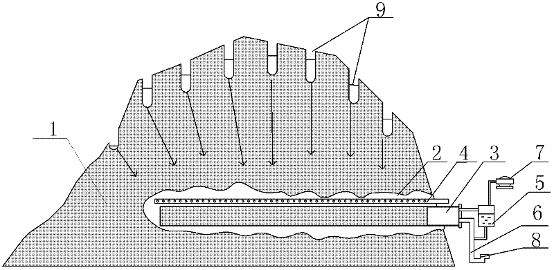
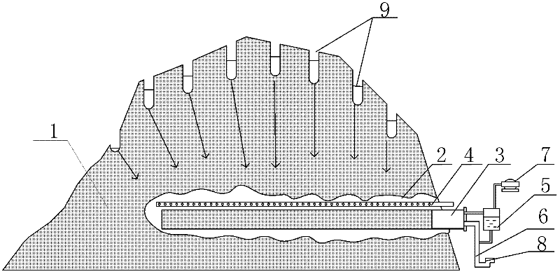
[0033] like figure 1 As shown, a 3×3m bottom plate is prepared for the simulated ore body bedrock, and there are small holes for water seepage on the bottom plate. According to the actual situation of the ore body, the ore soil is piled up on the simulated bedrock bottom plate to make an ion-adsorption type ore body model . Install a liquid injection pipe (equivalent to the liquid injection well 9) on the surface of the ore body model according to the in-situ leaching process, then excavate a horizontal well at the bottom of the ore body model, and set a rigid PVC porous pipe with a 200-mesh filter screen in the horizontal well as a vacuum The liquid outlet pipe 3 and the PE pipe parallel to the vacuum outlet pipe 3 are used as the porous grouting pipe 4 (5mm holes are opened every 0.05 meters on the pipe), the vacuum outlet ...

Embodiment 2

[0038] Example 2 is used to illustrate the efficiency of adopting the method of the present invention to carry out in-situ leaching ore extraction.

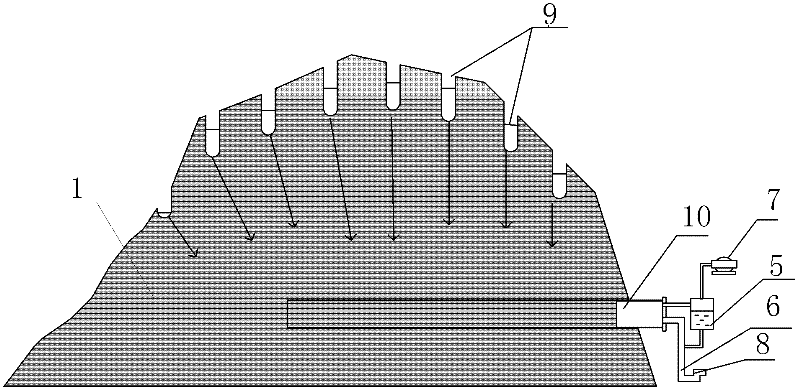
[0039] like figure 2 As shown, a 1×1m bottom plate is prepared for the bedrock of the simulated ore body, and there are small holes for water seepage on the bottom plate. According to the actual situation of the ore body, the ore soil is piled up on the bottom plate of the simulated bed rock to make an ion-adsorption type ore body model . According to the in-situ leaching process, a PE material injection pipe (equivalent to the liquid injection well 9) is installed on the surface of the ore body model, and a microporous ceramic tube 10 with an aperture of 0.5-2 μm is installed at the bottom of the ore body model, and the microporous ceramic One end of the pipe 10 is closed, and the other end is connected to the gas-water separator 5, and the gas-water separator 5 is connected to the vacuum system 7. Turn on the vacuum system 7...


PUM

PropertyMeasurementUnit
pore sizeaaaaaaaaaa
recovery rateaaaaaaaaaa

Abstract

The invention relates to a method of in-situ ore leaching and leachate discharge of ion adsorption type ore; the leachate is collected in a vacuum mode; a porous capillary leachate-guiding layer is disposed between the ore body and a vacuum leachate outlet and has the function of obstructing air; the leachate is transferred from the ore body to the vacuum leachate outlet under the vacuum pressure conducted by capillary action. The invention also provides a system for realizing the method. The method and system of the invention facilitate the improvement of vacuum leachate discharge area and system vacuum degree, greatly decrease the energy consumption required for maintaining vacuum, thus reduce the moisture capacity of the ore layer, enlarge the control range, and increase the leachate discharge efficiency.

Description

technical field [0001] The invention belongs to the field of wet metallurgy, and relates to a method and a system for ion-adsorption type ore in-situ leaching ore extraction. Background technique [0002] The ion-adsorbed ore in southern my country is rich in medium and heavy rare earths, which has high mining and application value, and is a unique treasure house of medium and heavy rare earths in the world. With the weathering of granite, rare earth ores are adsorbed on kaolin in the form of ions, which is easy to mine. [0003] At present, the leaching processes of ion-adsorbed ore mainly include pool leaching, heap leaching and in-situ leaching ore leaching. The pool leaching process is a method of exchanging the ore soil and the leaching agent in the pool, discarding the remaining soil and recovering the solution. The heap leaching process is to pile up ore soil on an impermeable platform after mining, rinse the leaching agent from the top of the pile, and collect the ...

Claims


Application Information

Patent Timeline
Patent Type & Authority Applications(China)
IPC IPC(8): C22B3/04C22B3/02
CPCY02P10/20
Inventor 吴声廖春生王嵩龄刘艳程福祥
Owner CHINA MINMETALS BEIJING RES INST OF RE
Why Eureka
Try Eureka