
Suspension type automatic blanking vertical and horizontal dual-purpose heat accumulation energy-saving reduction furnace

A vertical and horizontal dual-purpose reduction furnace technology, which is applied in furnaces, muffle furnaces, cooking furnaces, etc., can solve the problems of high energy consumption, thermal creep deformation and scrapping of reduction tanks, low production efficiency, etc. Furnace structure, high labor intensity of workers, and low production efficiency

Inactive Publication Date: 2012-03-28
李恒杰 +3
View PDF7 Cites 8 Cited by
  • Summary
  • Abstract
  • Description
  • Claims
  • Application Information

AI Technical Summary

Problems solved by technology

[0003] According to practice, this method of burning and heating a large furnace built with refractory bricks, because the space in the furnace is too large, the radius of heat radiation transfer is large, and the convection of high-temperature flue gas has dead angles, resulting in poor temperature uniformity and easy overheating of the reduction tank. Thermal creep deformation and scrapping requires manual loading and unloading of materials in each reduction cycle, which cannot realize mechanized and automatic loading and unloading. Therefore, the old-fashioned furnace built with refractory bricks has high labor intensity, high energy consumption, large floor space, and low production efficiency. , low reduction rate, short service life of the reduction tank, etc. The furnace body itself is built with refractory bricks. Generally, it will be repaired in about 3 months, and it will be overhauled and replaced in about a year, so the service life of the furnace body is short.

Method used


Image

  • Suspension type automatic blanking vertical and horizontal dual-purpose heat accumulation energy-saving reduction furnace
  • Suspension type automatic blanking vertical and horizontal dual-purpose heat accumulation energy-saving reduction furnace
  • Suspension type automatic blanking vertical and horizontal dual-purpose heat accumulation energy-saving reduction furnace

Examples


Embodiment Construction

[0040] Below in conjunction with accompanying drawing and embodiment the present invention will be further described:

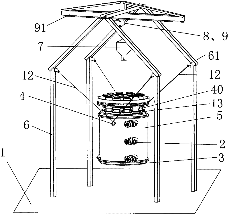
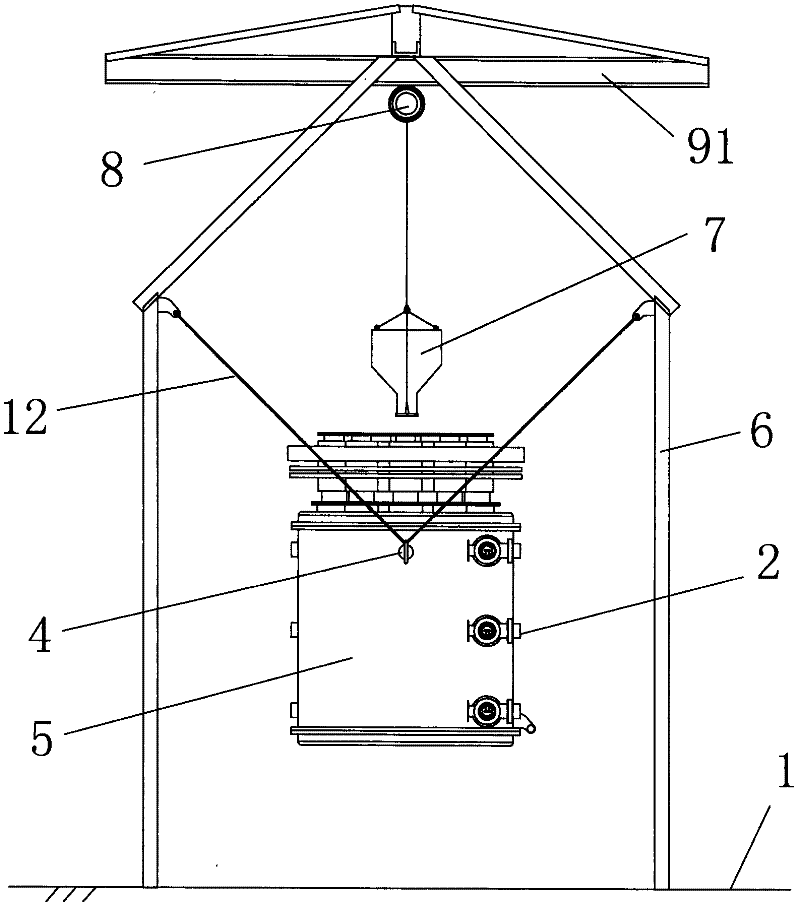
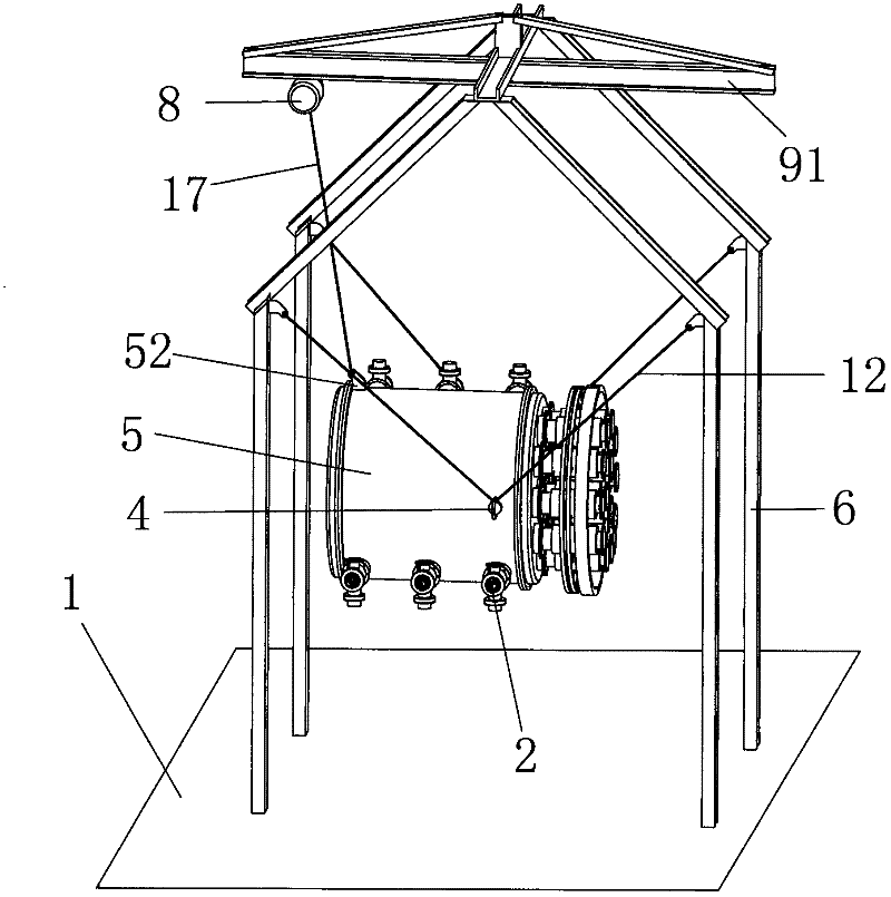
[0041] As shown in the figure, this reduction furnace is a suspension type, and the metal furnace body of the reduction furnace can be turned over. When the mouth of the reduction tank is facing up, the electric hoist can be used to mechanically load the material. When the mouth of the reduction tank is facing down, the end cover is removed, that is It can be unloaded by self-weight, and it can be fired horizontally or vertically. It is mainly composed of a reduction furnace metal furnace body, a reduction tank, a burner, a suspension device, a walking mechanism, a charging mechanism and a regenerator heat exchange device.

[0042] Such as Figure 1-4 As shown, the suspension device is mainly used for suspending the metal furnace body 5 of the reduction furnace, on which a walking mechanism 9 and a charging mechanism 7 for feeding materials are also arranged....


PUM


Abstract

The invention provides a suspension type automatic blanking vertical and horizontal dual-purpose heat accumulation energy-saving reduction furnace which comprises a metal furnace body of the reduction furnace, reduction pots, heat accumulation type burners and a suspension device, wherein one end of the metal furnace body of the reduction furnace is connected with a seal head, and the other end of the metal furnace body is connected with a reduction pot fixing flange; the reduction pots are uniformly distributed in the metal furnace body; the heat accumulation type burners are also symmetrically arranged on the circumference; a point of the center of gravity or a point of the eccentric center of gravity is also provided with a universal suspension ring; a suspension wire rope is suspended on the universal suspension ring; two ends of the suspension wire rope are obliquely pulled on the suspension device; a turnover suspension ring is also arranged on the metal furnace body of the reduction furnace near the seal head; the turnover suspension ring is connected with an electric block through a turnover wire rope; the metal furnace body of the reduction furnace turns under the pulling and relaxing operation of the turnover wire rope by taking the universal suspension ring of the furnace body as a center; and the suspension device comprises a portal frame, and the metal furnace body of the reduction furnace, the electric block, a running mechanism and a feeding mechanism are suspended on the portal frame.

Description

technical field [0001] The invention relates to a metal reduction furnace, and mainly refers to a suspended self-cutting, vertical and horizontal dual-purpose thermal storage and energy-saving reduction furnace for refining and reducing non-ferrous metals. Background technique [0002] The traditional magnesium smelting process is the Pidgeon method. This method uses a horizontal furnace. The furnace body is built on the ground with refractory bricks. Filled with pellets of reaction materials, coal or gas or oil is used as fuel, and manual loading and unloading is adopted for combustion and heating. The reduction tank is first heated by the radiant heat of the reverberatory furnace outside the reduction tank, and then the heat is radiated from the reduction tank to the reaction materials in the tank. The pellets, and then the pellets relay heat to each other, which is a kind of peripheral heating. [0003] According to practice, this method of burning and heating a large fu...

Claims


Application Information

Patent Timeline
Patent Type & Authority Applications(China)
IPC IPC(8): F27B14/04F27B14/08F27B14/14F27B14/20
CPCF27B14/04F27D17/004F27B17/00F27B14/14C22B26/22F27B14/20F27D99/0035F27B5/06
Inventor 李恒杰邓小宝劳志立邓凯峰
Owner 李恒杰
Learn More