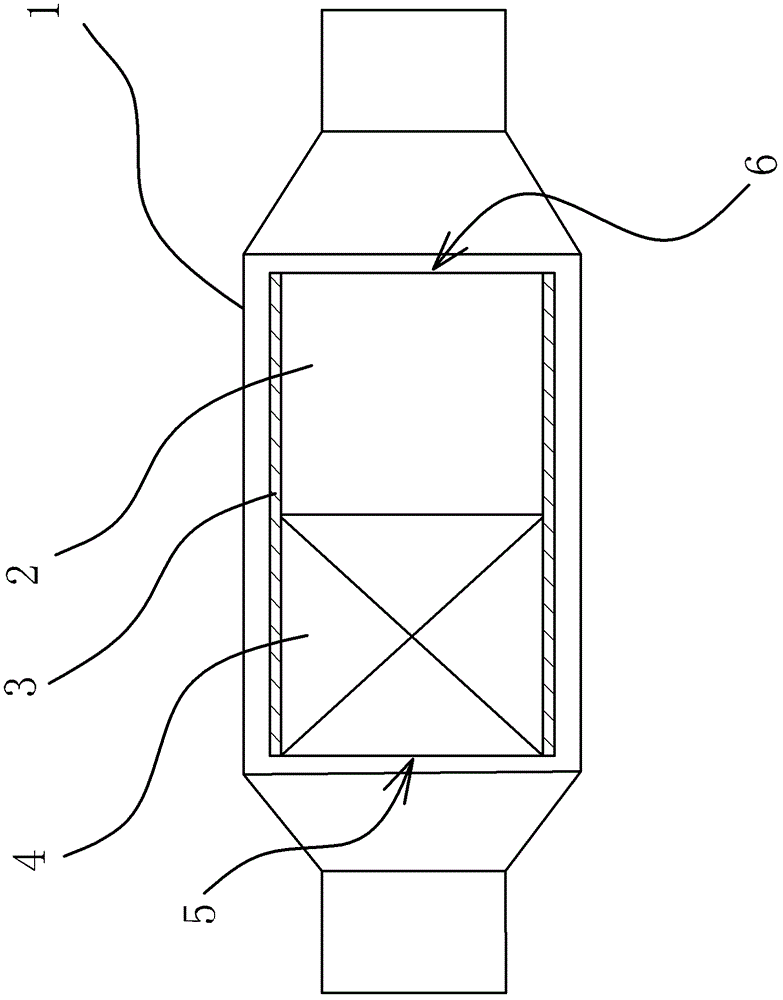
Ternary catalytic converter and method for coating catalytic layers thereof

A three-way catalyst, three-way catalyst technology, applied in coatings, engine components, machines/engines, etc., can solve the problems of high cost, low catalytic conversion efficiency, long light-off time, etc. The effect of reducing activity and improving processing capacity

Active Publication Date: 2013-10-16
ZHEJIANG GEELY AUTOMOBILE RES INST CO LTD +1
View PDF1 Cites 4 Cited by
  • Summary
  • Abstract
  • Description
  • Claims
  • Application Information

AI Technical Summary

Problems solved by technology

For example, the Chinese patent (authorized announcement number: CN201326446Y) discloses a carrier of a three-way catalytic converter, including a three-way catalytic converter and a carrier. The surface of the air inlet end of the carrier has a certain radius of curvature or a surface with a slope, and the catalyst Evenly coated on the inner surface of the carrier, although this method increases the exhaust gas processing capacity, it increases the contact area between the catalyst and the exhaust gas through the volume of the carrier to improve the exhaust gas processing capacity of the three-way catalytic converter. Relatively high, and the catalyst adopts the integral coating method, which requires a large amount of heat to make the catalyst fully reach the light-off temperature, which takes a long time to light-off, and the catalytic conversion efficiency is very low, which cannot solve the problem of three-way catalysis. The problem of the exhaust gas processing capacity when the engine is cold started

Method used


Image

  • Ternary catalytic converter and method for coating catalytic layers thereof

Examples


Embodiment 1

[0032] Take the carrier substrate of the three-way catalytic converter, place it vertically on the outlet of the grouting machine and make the feed port and the outlet of the grouting machine seal connected, the feed port is the air inlet of the carrier, and pass through the grouting machine Input a certain volume of slurry comprising three-way catalyst 1 into the carrier, so that the slurry is evenly coated on the area of ​​the catalytic layer 1 upwards from the bottom of the carrier, so that the total mass of precious metals of catalyst palladium and rhodium in the catalytic layer 1 100g / ft 3 , the weight ratio value of palladium and rhodium in the above-mentioned slurry that comprises three-way catalyst one is 20, and described slurry can adopt the conventional method preparation of this area to form, then discharge the slurry that is made more, and then apply The carrier covered with catalytic layer 1 is put into a roasting furnace for roasting, the temperature is raised t...

Embodiment 2

[0035] Take the carrier substrate of the three-way catalytic converter, place it vertically on the outlet of the grouting machine and make the feed port and the outlet of the grouting machine seal connected, the feed port is the air inlet of the carrier, and pass through the grouting machine Input a certain volume of slurry comprising three-way catalyst 1 into the carrier, so that the slurry is evenly coated upwards on the area of ​​catalytic layer 1 from the bottom of the air inlet of the carrier, forming catalytic layer 1, and making catalytic layer 1 The total mass of precious metals in the catalyst palladium and rhodium is 120g / ft 3 , the weight ratio value of palladium and rhodium in the above-mentioned slurry that comprises three-way catalyst one is 28, and described slurry can adopt the conventional method preparation of this area to form, and the slurry that is done more is discharged, and then will be coated with The carrier of the catalytic layer 1 is put into a roas...

Embodiment 3

[0038] Take the carrier substrate of the three-way catalytic converter, place it vertically on the outlet of the grouting machine and make the feed port and the outlet of the grouting machine seal connected, the feed port is the air inlet of the carrier, and pass through the grouting machine Input a certain volume of slurry comprising three-way catalyst 1 into the carrier, so that the slurry is evenly coated upwards on the area of ​​catalytic layer 1 from the bottom of the air inlet of the carrier, forming catalytic layer 1, and making catalytic layer 1 The total mass of precious metals in the catalyst palladium and rhodium is 120g / ft 3 , the weight ratio value of palladium and rhodium in the above-mentioned slurry that comprises three-way catalyst one is 24, and described slurry can adopt the conventional method preparation of this area to form, and the slurry of making more is discharged, and then will be coated with The carrier of the catalytic layer 1 is put into a roastin...


PUM


Abstract

The invention relates to a ternary catalytic converter and a method for coating catalytic layers thereof. The ternary catalytic converter comprises a shell and a carrier arranged in the shell, wherein a catalytic layer I prepared by adopting a ternary catalyst I and a catalytic layer II prepared by adopting a ternary catalyst II are sequentially coated on the inner surface of the carrier from an air inlet to an air outlet; and the ternary catalyst II has the precious metal content being lower than that in the ternary catalyst I. Compared with the prior art, the ternary catalytic converter has the advantages that because the catalysts are coated in a partitioning manner, the structure is novel, the integral catalytic performance of the catalytic converter is increased, the catalytic conversion rate of the ternary catalytic converter during cold start is increased, the integral catalytic conversion rate of the ternary catalytic converter is increased, and the pertinence and the catalytic performance are strong; in addition, the method for coating the catalytic layers of the ternary catalyst is simple in process, can be used for ensuring the coating uniformity of the catalysts and is suitable for actual industrial production.

Description

technical field [0001] The invention relates to an engine exhaust gas purification technology, in particular to a three-way catalytic converter and a coating method for a catalytic layer thereof. Background technique [0002] The three-way catalytic converter is the most important external purification device installed in the automobile exhaust system. It can convert harmful gases such as CO, hydrocarbons (HC) and NOx in the exhaust gas from the automobile into harmless gases through oxidation and reduction. Harmful carbon dioxide, water and nitrogen. [0003] The three-way catalytic converter includes a shell and a carrier. The carrier is set in the shell. The carrier part is made of a piece of porous ceramic material, or it can be made into a honeycomb structure. The real function of the three-way catalytic converter is not the carrier itself, but the Catalyst material composed of platinum, palladium, rhodium and other precious metals covered on the carrier. The catalyti...

Claims


Application Information

Patent Timeline
Patent Type & Authority Patents(China)
IPC IPC(8): F01N3/28B05C9/06B05C9/14B05D7/24
CPCY02T10/22Y02T10/12
Inventor 王杰丁勇杨安志金吉刚任颖睦赵福全
Owner ZHEJIANG GEELY AUTOMOBILE RES INST CO LTD
Why Eureka
Try Eureka