System and technology for producing fixed bed gas and fully recovering heat

A technology of full recovery and fixed bed, which is applied in the field of full recovery system and recovery process, can solve the problems of safety production threat, large system resistance, and increased cooling water consumption, so as to reduce cooling water consumption, steam consumption and coal consumption, The effect of increasing the gas production of a single furnace

Inactive Publication Date: 2012-04-18
ANHUI HUAIHUA
View PDF4 Cites 11 Cited by
  • Summary
  • Abstract
  • Description
  • Claims
  • Application Information

AI Technical Summary

Problems solved by technology

In recent years, the supply of high-quality lump coal has become increasingly tight. In order to reduce costs, low-quality lump coal and briquette coal are used for gas production. In terms of technology, only low furnace surface temperature operation method can be adopted. The corresponding blowing air temperature is less than 400 ℃, which is lower than the ignition point of blowing air. After replacing inferior raw materials, the temperature of the furnace surface is low. If the combustion chamber is filled with secondary air, explosion or incomplete combustion is likely to occur, which poses a threat to safe production.
Therefore, the single-boiler combustion chamber process can no longer be used to recover the latent heat of the blowing air, and can only be directly vented
[0018] 2. Although the blowing air recovers sensible heat through the waste heat boiler, the outlet temperature is still high at 200°C to 250°C, so it is directly discharged, and th

Method used


Image

  • System and technology for producing fixed bed gas and fully recovering heat
  • System and technology for producing fixed bed gas and fully recovering heat
  • System and technology for producing fixed bed gas and fully recovering heat

Examples


Embodiment Construction

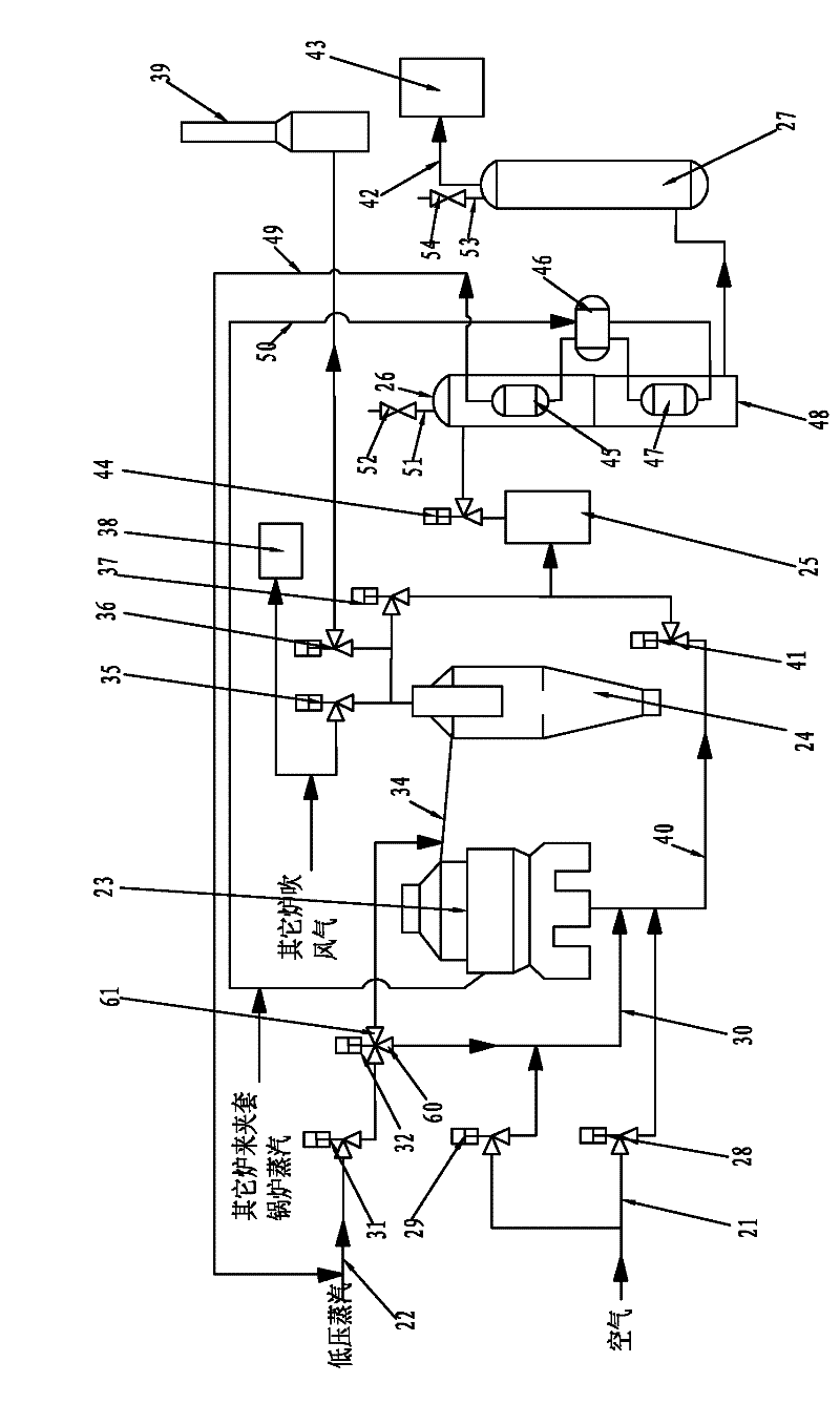
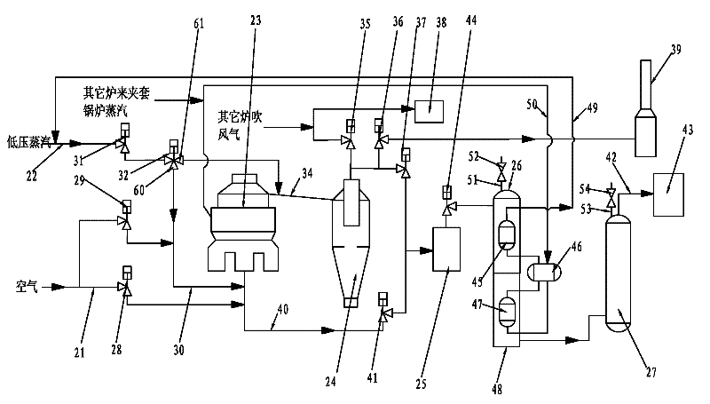
[0044] Such as figure 2 As shown, the fixed bed gas production and heat recovery system of the present invention includes an air main pipe 21, a low-pressure steam main pipe 22, a gas furnace 23, a dust collector 24, a dry water seal 25, a waste heat boiler 26, a scrubber 27, and an air main pipe 21 The outlet port of the gas furnace is communicated with the bottom of the gas furnace 23 and the inlet end of the upper blowing air pipe 30 through the primary air valve 28 and the upper blowing nitrogen air valve 29 respectively, and the steam main valve 31 and the steam three-way valve 32 are successively installed on the low pressure steam main pipe 22 , the inlet of the steam three-way valve 32 is connected with the outlet end of the low-pressure steam main pipe 22, the first and second outlets 60, 61 are connected with the inlet end of the upper blowing inlet pipe 30 and the upper airway 34 respectively, and the outlet of the upper blowing inlet pipe 30 The pipe communicates ...


PUM


Abstract

The invention discloses a system and a technology for producing a fixed bed gas and fully recovering heat. The system which comprises a total air tube, a total low pressure steam tube, a gas stove, a residual heat boiler, a gas washing tower, a deduster and a dry water seal is characterized in that: one outlet end of the total air tube is communicated with the bottom of the gas stove through a primary air valve, and the other outlet end of the total air tube is communicated with the inlet end of an upward blowing gas inlet tube through an upward nitrogen blowing air valve; a total steam valve and a steam triple valve are arranged on the total low pressure steam tube in order; a first outlet of the steam triple valve is connected with the inlet end of the upward blowing gas inlet tube, and a second outlet of the steam triple valve is connected with an upper gas channel; the outlet tube of the upward blowing gas inlet tube is communicated with the bottom of the gas stove; a gas outlet at the top of the gas stove is communicated with the gas inlet of the deduster through the upper gas channel; the gas outlet of the deduster, which is communicated with a blowing air concentration recovering device through a blowing air recovering valve and is communicated with a chimney through a chimney valve, is communicated with the inlet end of the dry water seal through an upward blowing gas valve; and the residual heat boiler is a combination heat tube boiler. According to the invention, heat in the gas production process can be completely recovered, so energy saving, environmental protection, safety and reliability are realized.

Description

technical field [0001] The invention relates to the field of coal gas preparation, in particular to a system and recovery process for producing raw material gases such as synthetic ammonia and methanol and heat by using the intermittent gasification technology of a fixed-bed coal gasifier. Background technique [0002] In the production process of gas, the gas furnace is divided into five stages in a working cycle: blowing, blowing up, blowing down, blowing up twice, and air blowing. [0003] Existing gas production systems such as figure 1 As shown, the process is as follows: [0004] Blowing stage: The air is pressurized by the blower and enters the gas furnace from the main air pipe 11 through the primary air valve 1. The oxygen in the air reacts with the carbon in the furnace to form carbon monoxide and carbon dioxide. heat. The blowing gas passes through the combustion chamber, and the solid particles brought out are settled. The gas enters the waste heat boiler thro...

Claims


Application Information

Patent Timeline
IPC IPC(8): C10J3/20C10J3/16C10J3/84C10J3/22C10J3/86
CPCY02P20/10Y02P20/129
Inventor 陆军周静
Owner ANHUI HUAIHUA
Why Eureka
Try Eureka