
Optical gyro based on flexible surface plasmon polariton waveguide

A plasma and flexible surface technology, applied in the field of optical gyroscopes, can solve the problems of inability to prepare ultra-long optical waveguide resonators, inability to replace fiber optic gyroscopes, inability to achieve high precision, etc. The effect of bending loss

Active Publication Date: 2014-01-01
SOUTHEAST UNIV
View PDF3 Cites 0 Cited by
  • Summary
  • Abstract
  • Description
  • Claims
  • Application Information

AI Technical Summary

Problems solved by technology

Although the integrated optical waveguide gyro can achieve a certain degree of integration, it still cannot replace the fiber optic gyroscope. The main reason is that the planar optical waveguide integration process cannot prepare ultra-long optical waveguide resonators, and the optical waveguide loss of the planar optical waveguide process is much higher. in optical fiber
Therefore, the current integrated optical waveguide gyroscope faces a technical bottleneck and cannot achieve high precision

Method used


Image

  • Optical gyro based on flexible surface plasmon polariton waveguide
  • Optical gyro based on flexible surface plasmon polariton waveguide
  • Optical gyro based on flexible surface plasmon polariton waveguide

Examples


Embodiment Construction

[0020] The present invention will be described below with reference to the accompanying drawings.

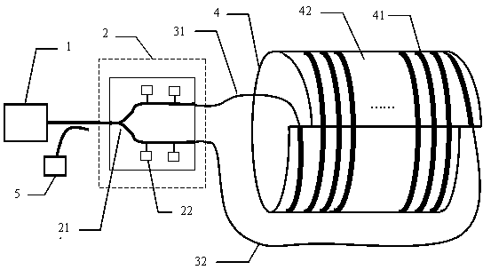
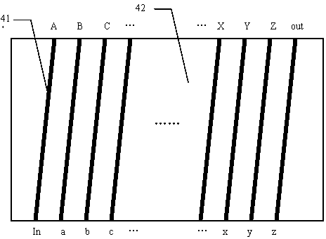
[0021] The optical gyroscope based on the surface plasmon flexible material optical waveguide of the present invention is realized in this way. The flexible material optical waveguide is prepared by utilizing the surface plasmon properties of the metal and the flexible polymer material. The waveguides all have the same width and spacing. The optical waveguide is crimped, and the end faces of the waveguide are butted and fixed, so that all the waveguides are connected into an ultra-long optical waveguide. The optical gyroscope based on the surface plasmon flexible material optical waveguide can be formed by connecting the optical waveguide to the optical gyro system instead of the optical fiber.

[0022] see figure 1 -3. The optical gyroscope based on the flexible surface plasmon waveguide provided by the present invention, the optical gyroscope includes a light source 1, a Y b...


PUM


Abstract

The invention relates to an optical gyro based on a flexible surface plasmon polariton waveguide. The optical gyro comprises a light source (1), a Y branched modulator (2), an input optic fiber (31), an output optic fiber (32), a flexible surface plasmon polariton waveguide cylindrical surface (4) and an optical detector (5), wherein the flexible surface plasmon polariton waveguide cylindrical surface (4) comprises a flexible surface plasmon polariton waveguide (41) and a flexible substrate (42); a light signal is output from the light source (1) to the Y branched modulator (2), subjected to modulation, and input from the input optic fiber (31) to the flexible surface plasmon polariton waveguide cylindrical surface (4); light is interfered in the flexible surface plasmon polariton waveguide (41) and transmitted from the output optic fiber (32) to the optical detector (5); and the rotational angular velocity is detected by the optical detector (5). The integration degree and the shock resistance of the optical gyro system are improved; and the structure of the optical gyro is simplified.

Description

technical field [0001] The present invention proposes an optical gyroscope that utilizes flexible surface plasmon waveguides to be bent and connected to long waveguides, especially relates to the design and preparation of flexible surface plasmon waveguides, which can replace traditional fiber optic gyroscopes, effectively reduce the volume and weight of gyroscopes, and be applied to optical gyroscopes field. Background technique [0002] As a new type of gyroscope, the optical gyroscope has performance advantages such as high sensitivity, flexible structure, and small volume and weight, and has attracted the attention of universities and scientific research institutions in many countries in the world. Optical gyroscopes use the Sagnac effect in a closed optical waveguide loop to measure the rotational angular velocity of a rotating body, including laser gyroscopes, fiber optic gyroscopes, and integrated optical waveguide gyroscopes. Laser gyroscopes use optical signals to ...

Claims


Application Information

Patent Timeline
Patent Type & Authority Patents(China)
IPC IPC(8): G01C19/72
Inventor 张彤李威张晓阳李若舟
Owner SOUTHEAST UNIV
Learn More