Three-phase power input open-phase detection circuit

A technology of lack of phase detection and three-phase power supply, which is applied in the field of frequency converters, can solve problems such as unreliability, wrong output, wrong pulse calculation, etc., and achieve the effects of strong low-level capability, simple circuit structure, and strong interference ability

Active Publication Date: 2012-04-25
GUANGZHOU SANJING ELETRIC
View PDF4 Cites 24 Cited by
  • Summary
  • Abstract
  • Description
  • Claims
  • Application Information

AI Technical Summary

Problems solved by technology

[0010] Because the circuit uses two optocouplers to detect the input voltage, the circuit cost is relatively high; and because the ordinary optocoupler itself has a conduction voltage drop of about 0.7V, when the output terminals of the two optocouplers are both turned on, the output of the detection circuit is the same as There is still a high voltage drop between the power supply and the ground, and the low level cannot be reliably output, so that in some low-voltage power supply occasions (such as the current control circuit with DSP as the main chip, the pin port voltage is usually 3.3V) , easy to be interfered and output incorrectly, or a level conversion circuit is required to connect with the main control circuit, which increases the complexity of the circuit
[0011] figure 2 The phase loss detection circuit shown also exists as previously described figure 1 Defect: It is necessary to calculate the number of square wave pulses by software and compare them with the set number of pulses, so as to judge whether the input is out of phase, which increases the complexity of the circuit and reduces the reliability of the circuit
[0013] image 3 improved figure 2 The pulse calculation error caused by the change of the input power supply frequency, and the problem of matching the output level with the low-voltage DSP, but it also increases the complexity and cost of the circuit, and the pulse counting method is still required to determine the detection result. There is no improvement in the case of program misjudgment caused by pulse interference or pulse loss

Method used


Image

  • Three-phase power input open-phase detection circuit
  • Three-phase power input open-phase detection circuit
  • Three-phase power input open-phase detection circuit

Examples


Embodiment 1

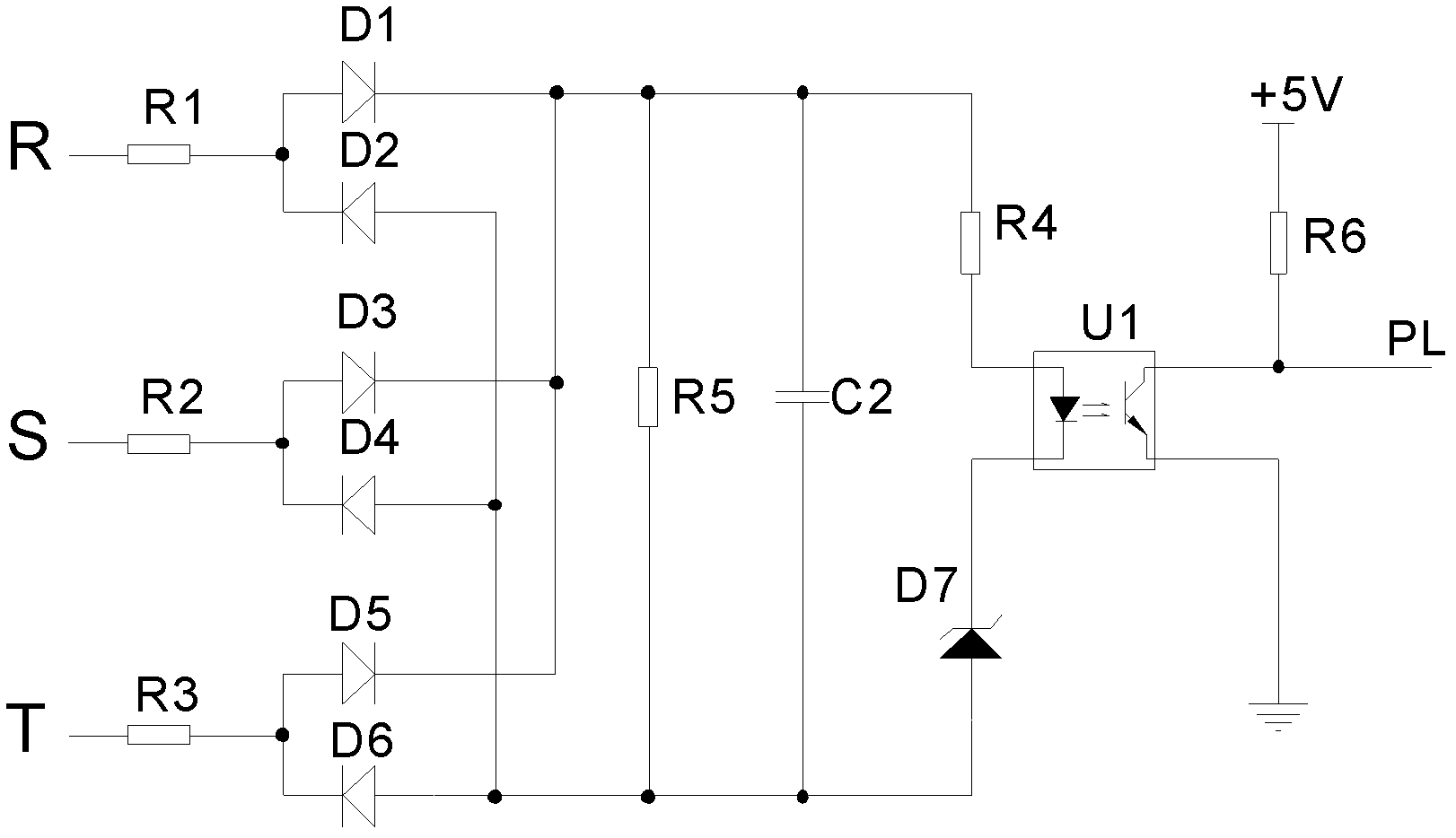
[0034] Such as Figure 4Shown is the circuit diagram of the three-phase power supply input phase loss detection circuit of the present invention, the phase loss detection circuit includes: first current limiting resistors respectively connected to the first phase line R, the second phase line S and the third phase line T R1, the second current limiting resistor R2 and the third current limiting resistor R3, the pull-up resistor R6 connected to the output terminal of the phase loss detection circuit; the first diode D1 connected to the first current limiting resistor R1, the second two Diode D2, connected to the third diode D3 and fourth diode D4 of the second current limiting resistor R2, connected to the fifth diode D5 of the third current limiting resistor R3; connected to the The cathode of the first diode D1 and the anode of the second diode D2 are connected to the cathode of the fifth diode D5 and the anode of the second diode D2. The second filter capacitor C2; one end ...

Embodiment 2

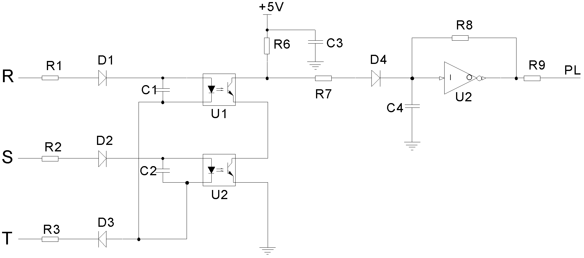
[0040] Such as Figure 5 As shown, in order to better protect the reliability of the circuit, a second Zener diode ZD2 connected in parallel with the second capacitor may also be included.


PUM


Abstract

The invention relates to a three-phase power input open-phase detection circuit, which comprises a first current limiting resistor, a second current limiting resistor a third current limiting resistor, a pull-up resistor, a first diode, a second diode, a third diode, a fourth diode, a fifth diode, a first filter capacitor, a first voltage stabilizing diode, a fourth current limiting resistor, an optical coupler, a triode, a fifth current limiting resistor and a second filter capacitor, wherein the first filter capacitor and the first voltage stabilizing diode are connected to the cathode of the first diode and the anode of the second diode; one end of the fourth current limiting resistor is connected to the cathode of the first diode; the output end collector of the optical coupler is connected to the pull-up resistor, and the output end emitter of the optical coupler is connected to signal ground; the collector of the triode is connected with the input end cathode of the optical coupler, the base of the triode is connected to the fifth current limiting resistor, and the emitter of the triode is connected with the anode of the second diode; one end of the fifth current limiting resistor is connected to the cathode of the fifth diode; and the second filter capacitor is connected to the cathode of the fifth diode and the anode of the second diode. The circuit overcomes the defects of high cost, complex software processing and low reliability in the conventional circuit.

Description

technical field [0001] The invention relates to the field of frequency converters, in particular to a three-phase power supply input phase loss detection circuit. Background technique [0002] Frequency conversion speed regulation has become the mainstream speed regulation method, and frequency converter is the core part of its speed regulation system. To ensure the reliable and safe operation of the inverter, it is necessary to provide various protections for the inverter. The input phase loss protection circuit, as the most commonly used and important protection circuit in the inverter, has been widely used in the inverter. [0003] Such as figure 1 Shown is a schematic diagram of a common inverter phase loss protection circuit. Three resistors (R1-R3) connected to the three-phase input terminal are used to limit the current of the three-phase power input, and six diodes (D1-D6) form a three-phase full-wave rectification circuit; the optocoupler U1 realizes the input ph...

Claims


Application Information

Patent Timeline
Patent Type & Authority Applications(China)
IPC IPC(8): G01R29/16G01R31/42
Inventor 李景志
Owner GUANGZHOU SANJING ELETRIC
Why Eureka
Try Eureka