
Ion-selective electrode flow injection analyser

A flow injection and analyzer technology, which is applied in the direction of material analysis, material analysis, and instrumentation by electromagnetic means, can solve the problems of large influence of environmental factors, inability to continuous analysis, long analysis time, etc., and achieve lower detection limit and stable potential. , the effect of small dead volume

Inactive Publication Date: 2013-06-12
QIQIHAR MEDICAL UNIVERSITY
View PDF1 Cites 0 Cited by
  • Summary
  • Abstract
  • Description
  • Claims
  • Application Information

AI Technical Summary

Problems solved by technology

At present, the ion selective electrode (ISE) analysis adopts the steady-state analysis method, which requires a large amount of reagents, a long analysis time, is greatly affected by environmental factors, and cannot be used for continuous analysis.

Method used


Image

  • Ion-selective electrode flow injection analyser

Examples


example 1

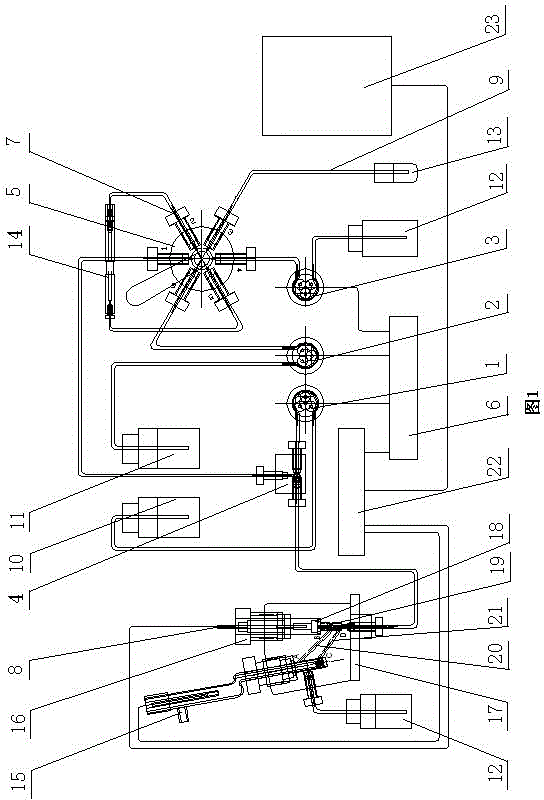
[0016] Such as figure 1 As shown, the ion selective electrode flow injection analyzer consists of a sample acquisition system, an ISE electrode system and a computer ISE software analysis system. The sample collection system consists of three peristaltic pumps 1, 2, 3, a six-way valve 4 and a separation column 14. The ISE electrode system includes a reference electrode 15, an electrode holder 17, an ISE electrode 8, a reflux tube 19 and a gravity gas-liquid separation device.

[0017] In the sample collection system, three peristaltic pumps 1, 2, and 3 are respectively connected to the control power supply 6, and each peristaltic pump is equipped with a microcatheter 7, and the three ports of the three-way valve 4 are respectively connected with a microcatheter 7. The screw is fixed, the left port is connected to the ISE electrode 8, the upper port is connected to the 1﹟ channel of the six-way valve 5, and the right port is connected to the peristaltic pump A1; the other end ...

example 2

[0019] In the ISE electrode system, the reference electrode 15 is fixed on the electrode frame 17 with a top wire 16 , the left end is fixed with a screw with a micro-catheter 7 , and connected to the waste liquid bottle 12 through the catheter 9 . The ISE electrode 8 is fixed on the electrode frame 17 with a top wire 16. The bottom end of the ISE electrode 8 is equipped with an ISE electrode film 18, and the bottom is a reflux tube 19 with a gap of 0.5 mm. The reference electrode 15 and the ISE electrode 8 pass through A-B The gravity separator composed of channel 20 and C-D channel 21 is connected, wherein the inclination angles of A-B channel 20 and C-D channel 21 are 35o and 45o respectively. The channels on both sides of the reflux pipe 19 are connected with the B and D ends of the gravity separator. The reference electrode 15 and the ISE electrode 8 are connected to a computer 23 with ISE analysis software through an analysis instrument signal interface 22 .

[0020] TI...


PUM


Abstract

The invention discloses an ion-selective electrode flow injection analyser. Ports of a three-way valve are connected with an ion selective electrode (ISE), a No.1 channel of a six-way valve and a peristaltic pump; the other end of the peristaltic pump A is connected with a total ionic strength adjustment buffer (TISAB) bottle; two ends of a peristaltic pump B are connected with a carrier liquid bottle and a No.6 channel; two ends of a peristaltic pump C are connected with a waste liquor bottle and a No.4 channel; a sample liquid bottle is connected with a No.3 channel; two ends of a separation column are connected with a No.2 channel and a No.5 channel; the bottom end of the ISE is provided with an ISE electrode membrane, a reflux tube is arranged below the ISE electrode membrane, and a gap between the reflux tube and the ISE electrode membrane is 0.5mm; a reference electrode and the ISE electrode are connected through a gravity separator consisting of an A-B channel and a C-D channel; inclination angles of the A-B channel and the C-D channel are 35 degrees and 45 degrees; and channels on two sides of the reflux tube are connected with the ends B and D of the gravity separator. The ion-selective electrode flow injection analyser has the advantages that: experimental reagents are saved, a detection line can be reduced, and a phenomenon that the detection limit is improved due to the dissolution of a salt type ISE membrane is inhibited.

Description

technical field [0001] The invention relates to an ion selective electrode flow injection analyzer, which belongs to the technical field of electrochemical analysis instruments. Background technique [0002] Flow Injection Analysis (FIA) is a new continuous flow analysis technique proposed by Danish chemists in 1974. This technique is to inject a certain volume of sample solution into a flowing, non-air-spaced reagent solution carrier stream, and the injected sample solution flows into the reaction coil to form a region and mix with the reagent in the carrier stream , reaction, and then enter the flow detector for measurement, analysis and recording. At present, the ion-selective electrode (ISE) analysis uses a steady-state analysis method, which requires a large amount of reagents, a long analysis time, is greatly affected by environmental factors, and cannot be used for continuous analysis. Contents of the invention [0003] The technical problem to be solved by the pr...

Claims


Application Information

Patent Timeline
Patent Type & Authority Patents(China)
IPC IPC(8): G01N27/416
Inventor 王静秦伟张榕庞磊王海君李红梅李爽
Owner QIQIHAR MEDICAL UNIVERSITY
Learn More