Method of laser machining of fiber-reinforced composite material and product made by the method

A laser processing method and composite material technology, which is applied in the field of laser processing and processing components of fiber-reinforced composite materials, can solve problems such as slow processing speed, difficult welding/joining processing, loose fiber processing costs, etc., and achieve high joint strength.

Inactive Publication Date: 2012-05-02
沓名宗春
View PDF5 Cites 40 Cited by
  • Summary
  • Abstract
  • Description
  • Claims
  • Application Information

AI Technical Summary

Problems solved by technology

However, it is known that since the base material and reinforcing fibers in composite materials such as CFRP and FRM are of different materials, it is not only difficult to perform removal processes such as cutting, drilling, and grooving, but also welding / joining processes are very difficult. difficulty
For example, there is concern that during diamond cutting or grinding, carbon fibers are scattered in the air to deteriorate the production environment
In addition, the processing speed is slow and the processing cost is high
Therefore, there is a problem that as a mass product other than aircraft, it has not been sufficiently used in addition to leisure products such as golf clubs and fishing rods
In addition, the problem of loose fibers on the cutting surface and high processing costs are also the main factors hindering the expansion of its application field.

Method used


Image

  • Method of laser machining of fiber-reinforced composite material and product made by the method
  • Method of laser machining of fiber-reinforced composite material and product made by the method
  • Method of laser machining of fiber-reinforced composite material and product made by the method

Examples


no. 1 example

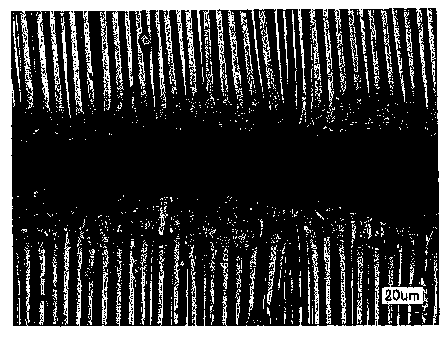
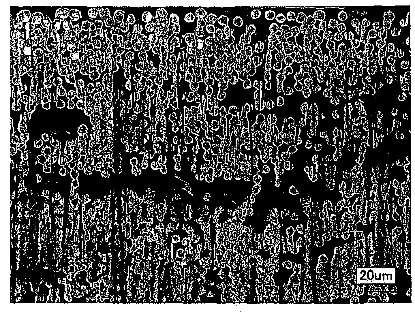
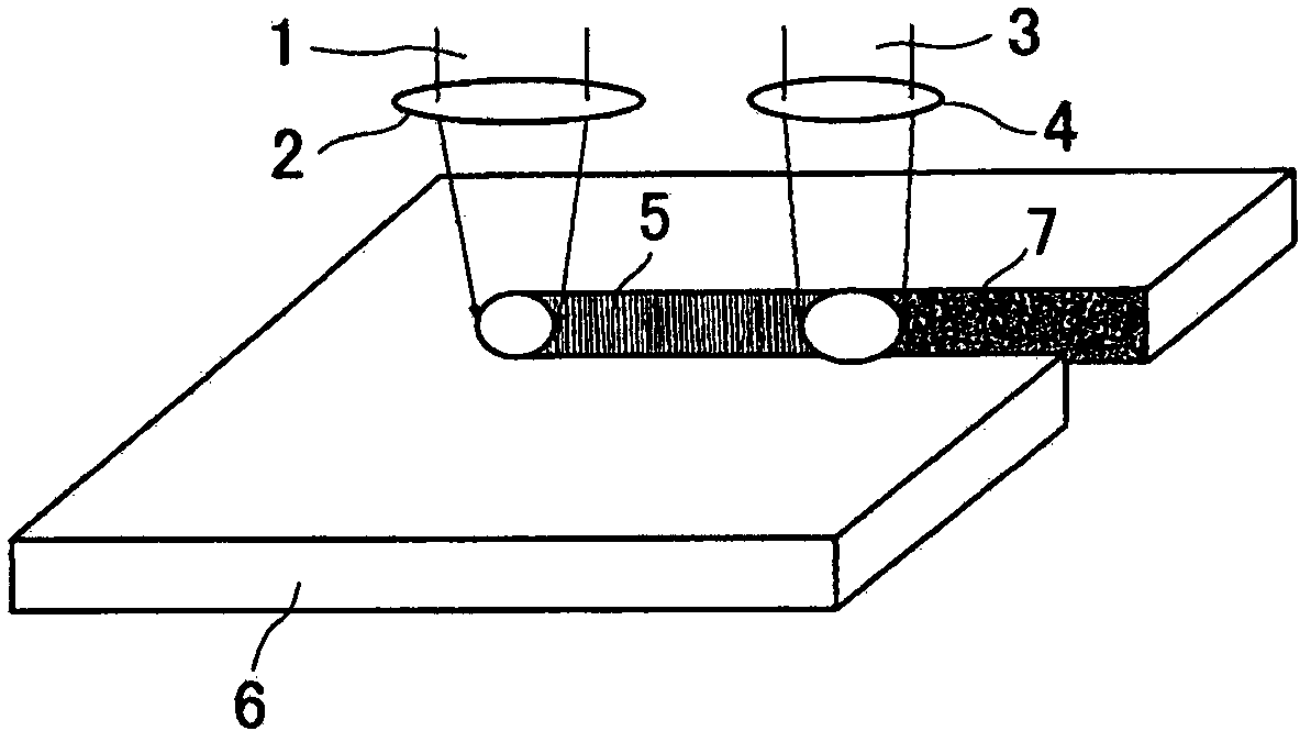
[0040] In the first embodiment, a cutting method using only an ultrashort pulse solid-state laser, a double-sided double laser cutting method, and a single-sided double laser cutting method will be described. Generally, if a composite material 6 such as CFRP is laser cut with a high-power continuous oscillating solid-state laser 1 (such as a fiber laser), it will be as follows: Figure 10 The carbon fibers are shown stripped and their tips melted and carbonized into a ball. If it is cut with an ultrashort pulse laser of 100 picoseconds to 50 nanoseconds (for example, a nanosecond pulse laser of 10 nanoseconds) 3, the laser will act on the electrons in the atomic structure of the object in an instant, heating the surface of the object to Tens of thousands of degrees. Since the time width of the pulse is shorter than the thermal diffusion time of the substance, heat accumulation is generated on the surface, and heat is generated only near the irradiated surface of the material ...

no. 2 example

[0044] In the second embodiment, a cascade cutting method using an ultrashort pulse laser will be described. image 3 Shown is a method of cutting a composite material with a thick plate, wherein the laser pass is divided into a fraction of the entire cutting line within the entire cutting line, and the first cascade cutting is performed from the surface 8, the second The second cascade cutting 9, the nth cascade cutting 10, and then the (n+1)th cascade cutting 11, the (n+2) cascade cutting 12, and the (n+3)th Cascade cutting13. This is called the ultrashort pulse laser cascade cutting method in this paper. This is due to the fact that ultrashort pulse lasers remove as little as a few cubic millimeters of material in one pass. But because of this, the quality of its cut surfaces is very high, making it a Figure 11 The cut surface shown.

[0045] For this reason, the pulse repetition frequency of the ultrashort pulse laser is preferably in the range of several kHz to sever...

no. 3 example

[0047] Figure 4 Indicates an inlay splice. Wherein, 14 is composite material A, 15 is composite material B or metal material, and 16 is the groove surface of welding seam forming. Preferred shapes for weld forming grooves for composite materials or composite laminates include, using the techniques of the first and second embodiments, the shape of the weld forming grooves. , known as a suitable joint for composites or composite laminates.

[0048] Figure 6 A single-layer material and a multi-layer material of an inlaid joint obtained by welding such a joint are shown.

[0049] Among them, 20 is a single-layer material for inlaid and spliced ​​joints, 21 is a multi-layer material for inlaid and spliced ​​joints, 22 is a multi-layer material for inlaid and spliced ​​joints (the first layer), 23 is a multi-layer material for inlaid and spliced ​​joints (the second layer), and 24 is Inlaid joint multilayer material (the third layer), 25 is the inlaid joint multilayer material...


PUM

PropertyMeasurementUnit
wavelengthaaaaaaaaaa

Abstract

A method of laser machining of a fiber-reinforced composite material of the present invention is characterized in that the fiber-reinforced composite material or composite ply material (ply material consisting of plates of metal or inorganic material and fiber-reinforced material) is cut using an ultra short pulse solid-state laser having a pulse-width ranging from 10 pico to 100 nano second and a pulse energy of 1mJ-500J, repeatedly irradiated to the material with the number of frequency ranging from 10Hz to 100kHz. According to the present invention, it is possible to work, e.g., cut, pierce, groove, or carve a fiber-reinforced composite material including CFRP, by removing materials by means of a laser with a high precision and good quality. It is also possible to form a fitting joint of proper shape so that a male-female joint may be available in a butt welding that has been hardly feasible. It is further possible to produce structural members such as a light weight panel or an H-column because the male-female joint can be used for a plate of any desired dimension (width, length and thickness).

Description

technical field [0001] The invention relates to a laser processing method of fiber-reinforced composite materials and components obtained by said laser processing method. In particular, it relates to a laser processing method and a processing component of CFRP or CFRM composite materials which are difficult to process. Background technique [0002] In order to solve the current energy problems, environmental problems, and resource problems in industries such as automobiles, aircraft, ships, and railway vehicles, it is increasingly required to realize light weight, high performance, high efficiency, resource saving, and recycling. The development of new materials and their processing technologies. [0003] In recent years, as the development of lightweight transportation equipment has become urgently needed, various composite materials are being adopted, among which CFRP has been applied to many parts of the fuselage in the aviation industry. [0004] In the prior art, dril...

Claims


Application Information

Patent Timeline
Patent Type & Authority Applications(China)
IPC IPC(8): B23K26/00B23K26/12B23K26/14B23K26/32B23K26/36B23K26/38B23K26/40B23K26/16B23K26/382
CPCB23K26/40B23K26/38B23K26/0635B23K26/0624B23K2103/16B23K2103/18B23K2103/40B23K26/12B23K2103/50
Inventor 沓名宗春
Owner 沓名宗春
Why Eureka
Try Eureka