Planar oxygen sensor and method for producing same

An oxygen sensor and oxygen sensing technology, which is applied in the direction of instruments, scientific instruments, measuring devices, etc., can solve the problems of unstable output voltage signal of oxygen sensor and low yield rate of oxygen sensor, and achieve stable air pressure, not easy to deform, and voltage signal stable effect

Active Publication Date: 2012-05-30
BYD CO LTD
View PDF3 Cites 13 Cited by
  • Summary
  • Abstract
  • Description
  • Claims
  • Application Information

AI Technical Summary

Problems solved by technology

[0004] The invention solves the technical problems in the prior art that the existence of the U-shaped air groove in the preparation process of the chip oxygen sensor leads to low oxygen sensor yield and unstable output voltage signal of the oxygen sensor

Method used


Image

  • Planar oxygen sensor and method for producing same
  • Planar oxygen sensor and method for producing same
  • Planar oxygen sensor and method for producing same

Examples


preparation example Construction

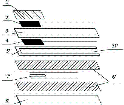
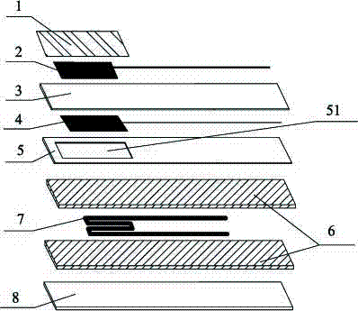
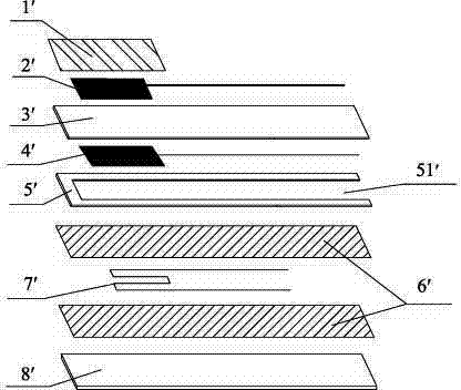
[0017] The present invention also provides a preparation method of a chip oxygen sensor, which comprises firstly cutting a through hole on the reference gas layer, then stacking the heating layer, the reference gas layer and the sensing layer in order from bottom to top, hot pressing and sintering to form a closed reference cavity at the through hole to obtain the chip oxygen sensor.

[0018] Specifically, the following steps are included:

[0019] 1) Take a heater substrate, print insulating layer paste, electrode paste, and insulating layer paste on the heater substrate in sequence, and dry to form an insulating layer on the heater substrate to obtain a heating layer;

[0020] 2) Print electrode paste on both sides of the zirconia sensitive substrate and dry to form electrodes on both sides of the zirconia sensitive substrate; then print a porous protective layer on one side of the electrode and dry to form a porous protective layer on the surface the sensing layer;

[002...

Embodiment 1

[0030] (1) Raw material preparation:

[0031] Insulating layer slurry: 75 parts by weight of aluminum oxide, 3 parts by weight of silicon oxide, 5 parts by weight of magnesium oxide, 15 parts by weight of terpineol, and 2 parts by weight of ethyl cellulose.

[0032] Electrode slurry: 81 parts by weight of Pt powder, 2 parts by weight of alumina, 2 parts by weight of zirconia, 10 parts by weight of terpineol, and 5 parts by weight of ethyl cellulose.

[0033] Porous protective layer slurry: 54 parts by weight of magnesium aluminum spinel, 30 parts by weight of alumina, 8 parts by weight of terpineol, 2 parts by weight of ethyl cellulose, and 6 parts by weight of a pore-forming agent.

[0034] (2) Print insulating layer slurry, electrode slurry, and insulating layer slurry on the zirconia cast sheet in sequence, and dry to obtain a heating layer.

[0035] (3) Cut a through hole on the zirconia cast sheet, the area of ​​the through hole accounts for 8% of the total area of ​​the...

Embodiment 2

[0039] The chip type oxygen sensor chip S2 of this embodiment was prepared by the same method as that of Example 1, the difference being that:

[0040] In step (3), the area of ​​the through hole accounts for 5% of the total area of ​​the reference gas layer.


PUM

PropertyMeasurementUnit
thicknessaaaaaaaaaa
thicknessaaaaaaaaaa

Abstract

The invention provides a planar oxygen sensor, which comprises a heating layer, a reference gas layer and a sensing layer sequentially from bottom to top. The planar oxygen sensor is characterized in that the reference gas layer is provided with through holes, and closed reference cavities are formed at the through holes of the heating layer, the reference gas layer and the sensing layer. The reference gas layer is provided with the through holes, so that the combination area of the reference gas layer with the upper layer and the lower layer is enlarged, and product yield can be increased effectively. In addition, the sensing layer, the reference gas layer and the heating layer are stacked to form the closed reference cavities, so that voltage signals outputted by the planar oxygen sensor are stable.

Description

technical field [0001] The invention relates to a chip oxygen sensor and a preparation method thereof. Background technique [0002] The automotive oxygen sensor is a key component that feeds back the combustion gas condition to the engine control unit (ECU) in real time, and the electronically controlled injection system of the engine precisely controls the air-fuel ratio based on the signal provided by the oxygen sensor. Once the air-fuel ratio of the mixture deviates from the theoretical value, the purification ability of the three-way catalyst will drop sharply, so an oxygen sensor is installed in the exhaust pipe to detect the concentration of oxygen in the exhaust gas, and send a feedback signal to the ECU, which is then controlled by the ECU The increase or decrease of the fuel injection quantity of the injector adjusts the air-fuel ratio (A / F, the mass ratio of air to gasoline) of the mixture near the theoretical value. Existing automotive oxygen sensors are mainly ...

Claims


Application Information

Patent Timeline
Patent Type & Authority Applications(China)
IPC IPC(8): G01N27/409
Inventor 黄志彬向其军
Owner BYD CO LTD
Why Eureka
Try Eureka