Numerical control spherical lathe

A spherical lathe and spindle technology, applied in the field of machine tools, can solve the problems of unstable sphericity, high equipment cost, and only semi-finishing, etc., to reduce the process and turnover storage, improve the quantity and quality, and reduce the replacement time Effect

Active Publication Date: 2012-06-20
南京肯迈得机床制造有限公司
View PDF6 Cites 9 Cited by
  • Summary
  • Abstract
  • Description
  • Claims
  • Application Information

AI Technical Summary

Problems solved by technology

[0011] d. The cutting of the tool in the R radius direction is controlled by manual compensation, the cutting consistency is poor, and automatic compensation control is not possible
[0012] e. Cannot do multi-tool automatic tool change
[0013] f. The protection ability is weak, wet cutting is not possible, and the production environment is very poor
[0014] 2. Disadvantages of imported spherical special equipment
[0015] a. Disadvantages of hydraulic presses
[0016] (1) Lack of multi-tool replacement processing, only semi-finishing and fine cutting
[0017] (2) The tool wear needs to be artificially determined with a dial gauge to determine the compensation amount, and the scrap rate is high
[0018] (3) The repeated positioning of the double turntable will deviate from the center of the circle, and the sphericity is unstable
[0019] (4) Poor protection ability
[0021] (1) The R radius direction of the turntable cannot be automatically controlled by the program, and has the same disadvantages as the hydraulic machine
[0022] (2) The cost of equipment is high, the return rate of function is low, the automatic tool compensation in the R direction cannot be achieved, and the polar coordinate processing and multi-continuous variable-diameter ball processing cannot be performed.
[0023] (3) Due to the need to switch the turntable, as the wear gap of the X-axis screw becomes larger, the ellipticity will also increase greatly

Method used


Image

  • Numerical control spherical lathe
  • Numerical control spherical lathe
  • Numerical control spherical lathe

Examples


Embodiment Construction

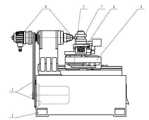
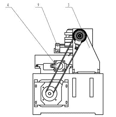
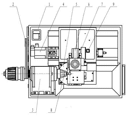
[0048] The present invention will be further described below in conjunction with two embodiments. in Figure 1-Figure 5 is a schematic diagram of embodiment 1, Figure 6-10 It is the schematic diagram of embodiment 2.

[0049] As shown in the figure, the CNC spherical lathe of the present invention has a main structure including a base 1, a servo motor 2 is arranged in the base 1, a main shaft assembly 3 is arranged on the base 1, and the main shaft assembly 3 communicates with the servo motor through a reduction transmission device. 2 connection, a workpiece clamping unit 8 is installed at the front end of the main shaft assembly 3; it is characterized in that a Z-axis center positioning unit 4 is provided on the base 1, a Y-axis rotation unit 5 is installed on it, and a Y-axis rotation unit 5 is installed on the Y-axis rotation unit 5. The X-axis radius feed unit 6 is equipped with a tool rest and a conversion unit 7 on the upper part of the X-axis radius feed unit 6 .

...


PUM

PropertyMeasurementUnit
Circularityaaaaaaaaaa

Abstract

The invention discloses a numerical control spherical lathe, which comprises a base. A servo motor is arranged in the base, a spindle assembly is arranged on the base and connected with the servo motor through a speed reducing transmission device, and a workpiece clamping unit is installed at the front end of the spindle assembly. A Z-axle circle center locating unit is arranged on the base, a Y-axle rotating unit is installed on the Z-axle circle center locating unit, an X-axle radius feeding unit is installed on the Y-axle rotating unit, and the upper portion of the radius feeding unit is provided with a knife rest and a knife rest converting unit. The numerical control spherical lathe adopts a multiple-axle lathe system with a single coordinate system controlled by five shafts and the normal cutting principle. A cutting tool always aligns at the circle center like the fact that a compass describes a circle around a point, and accordingly the roundness is very high. When the numerical control spherical lathe performs processing, a cutting edge cutting error and an interpolation error which are caused by quadrant left-and-right cutting when an ordinary numerical control lathe cuts a round sphere do not occur, wherein the errors include tool marks of program translation and pause in quadrant passing process.

Description

[0001] technical field [0002] The invention relates to a machine tool, in particular to a numerically controlled spherical lathe, which can be widely used in processing spherical joint bearings, various ball pins and connecting rod ball pins of automobile chassis, ball cores of ball valves in the plumbing valve industry, and human bodies. Bone joints made of bones, spherical injection pumps in hydraulic pumps, optical molds and lamps, etc. Background technique [0003] At present, the lathes used to process spherical surfaces mainly come from two sources: existing lathe modification and imported special equipment, among which: [0004] 1. The modification of the existing lathe is to modify the cross carriage of the original lathe on the general machine tool, add a turntable to the cross carriage and hang it on the semi-automatic tool feed of the X axis to complete the work of normal arc processing; the turntable is fixed A tool holder or a pair of small pallets for ma...

Claims


Application Information

Patent Timeline
Patent Type & Authority Applications(China)
IPC IPC(8): B23B5/40B23Q5/10B23Q5/34
Inventor 顾伟亮
Owner 南京肯迈得机床制造有限公司
Why Eureka
Try Eureka