
Manufacturing method of convective acceleration sensor chip based on temperature sensitive resistor

A technology of acceleration sensor and sensitive resistor, which is applied in the direction of acceleration measurement using inertial force, the process for producing decorative surface effects, and the manufacture of microstructure devices, etc. It can solve problems such as complex connections, achieve good reliability, and meet marketization demand, to achieve the effect of cost reduction

Active Publication Date: 2012-07-11
SHANGHAI INST OF MICROSYSTEM & INFORMATION TECH CHINESE ACAD OF SCI
View PDF5 Cites 9 Cited by
  • Summary
  • Abstract
  • Description
  • Claims
  • Application Information

AI Technical Summary

Problems solved by technology

However, the heating wire and temperature sensor of the accelerometer are supported by ordinary silicon dioxide or silicon nitride, suspended above the inner cavity formed by the single crystal silicon wafer, and packaged in the outer cavity formed by the tube shell and the shell cap. In the body, this structural design enables gas heat convection to occur between the inner and outer chambers; and it is also necessary to connect the pins of each temperature sensor outside the tube shell to form a more complex detection circuit

Method used


Image

  • Manufacturing method of convective acceleration sensor chip based on temperature sensitive resistor
  • Manufacturing method of convective acceleration sensor chip based on temperature sensitive resistor
  • Manufacturing method of convective acceleration sensor chip based on temperature sensitive resistor

Examples


Embodiment Construction

[0043] The present invention will be described in further detail below in conjunction with the accompanying drawings.

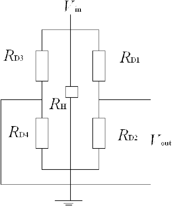
[0044] The thermal convection acceleration sensor made in this embodiment is based on temperature-sensitive resistors and adopts four polysilicon temperature-sensitive resistors. The heat source (heater) is composed of polysilicon heating resistors, and the heating resistors are suspended in the middle of the sealed cavity. At zero time, an isothermal convection field is formed in the cavity; when there is acceleration, a small air mass is caused to convect freely, forming a temperature gradient field in the cavity. Two pairs of polysilicon temperature-sensitive resistors are placed on both sides of the heater equidistantly and symmetrically (coaxially), and are connected to form a Wheatstone detection bridge. Since the temperature sensitive resistors on both sides are subjected to different temperatures, the temperature sensitive resistors undergo different ...


PUM

PropertyMeasurementUnit
Thicknessaaaaaaaaaa
Thicknessaaaaaaaaaa
Thicknessaaaaaaaaaa

Abstract

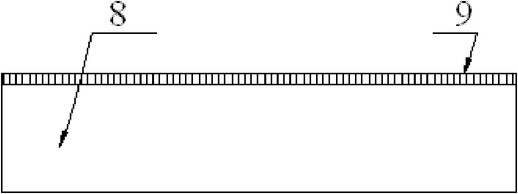
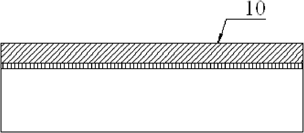
The invention provides a manufacturing method of convective acceleration sensor chip based on a temperature sensitive resistor. The method comprises the following steps: firstly, forming an oxide layer and a low stress silicon nitride layer on the surface of a mono-crystalline silicon wafer; manufacturing the polycrystalline silicon temperature sensitive resistor and a polycrystalline silicon heating resistor on the low stress silicon nitride layer; manufacturing metal interconnection lines to form an acceleration sensor output circuit; corroding the mono-crystalline silicon wafer to form a concave cavity, releasing a cantilever; bonding a cover on the silicon wafer by a BCB (benzo cyclobutene) adhesive to form a sealed cavity, finally the acceleration sensor chip is obtained. The method of the invention uses the low stress silicon nitride layer deposited by LPCVD (low pressure chemical vapor deposition) as a supporting layer of the heating resistor and the temperature sensitive resistor, and manufactures the polycrystalline silicon heating resistor and the polycrystalline silicon temperature sensitive resistor by an LPCVD and doping technology; the manufactured convective acceleration sensor chip has the advantages of high detection precision, high reliability and good stability; and the manufacturing technology is compatible with IC (integrated circuit) technology. In this way, the method of the invention is helpful for realizing chip microminiaturization and low cost.

Description

technical field [0001] The invention relates to a method for manufacturing a thermal convection acceleration sensor chip, in particular to a method for manufacturing a thermal convection acceleration sensor chip based on a temperature-sensitive resistor, and belongs to the technical field of silicon micromechanical sensors. Background technique [0002] Accelerometers based on silicon micromachining technology have the advantages of small size, light weight, high performance, and low cost due to mass production. They have been used in many testing occasions, such as automotive airbags, crash tests, and consumer electronics. , seismic wave detection, military inertial technology navigation, etc. Explosion, shock test and penetrating bomb fuze are one of the very special applications. The acceleration to be detected can be as high as tens of thousands of g or even hundreds of thousands of g. Accelerometers are required not only to have high sensitivity, but also to have high r...

Claims


Application Information

Patent Timeline
IPC IPC(8): B81C1/00G01P15/12
Inventor 李昕欣王权
Owner SHANGHAI INST OF MICROSYSTEM & INFORMATION TECH CHINESE ACAD OF SCI
Learn More