Conductive rubber roller and imaging device
A technology for rubber rollers and rubber layers, applied in the direction of electrography, electrical recording technology using charge patterns, equipment for electric recording technology using charge patterns, etc., can solve the difference in the hardness and resistance of rubber rollers in the lateral direction of the circumferential direction, The process has a great influence and affects the printing effect, etc., to achieve the effect of stable electrical performance, uniform resistance distribution, and good image quality
- Summary
- Abstract
- Description
- Claims
- Application Information
AI Technical Summary
Problems solved by technology
Method used
Image

Examples
Embodiment 1
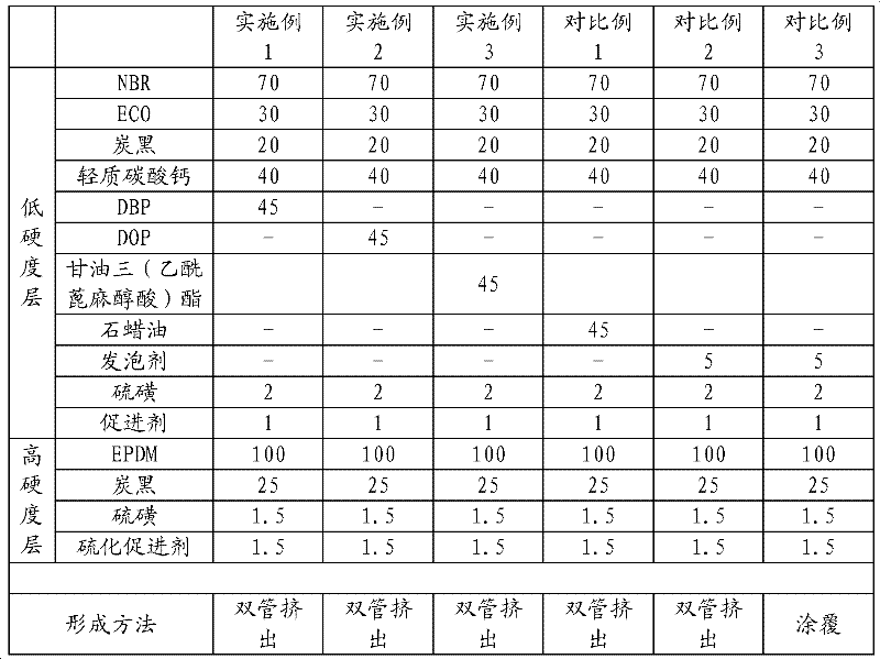
[0031] Nitrile rubber [δ C =19.2(J / cm 3 ) 1 / 2 ] 70 parts, epichlorohydrin rubber [δ C =19.8(J / cm 3 ) 1 / 2 ]30 parts, carbon black 20 parts, dibutyl phthalate [δ A =19.72(J / cm 3 ) 1 / 2 ] 45 parts, 40 parts of light calcium carbonate, 2 parts of sulfur, 1 part of vulcanization accelerator, it is mixed uniformly with open type rubber mixing machine or closed type rubber mixing machine according to conventional method, obtains rubber composition I.
[0032] The EPDM rubber ([δ B =16.2(J / cm 3 ) 1 / 2 ] 100 parts, 25 parts of carbon black, 1.5 parts of sulfur, and 1.5 parts of vulcanization accelerator were uniformly mixed in the same manner as above to obtain rubber composition II.
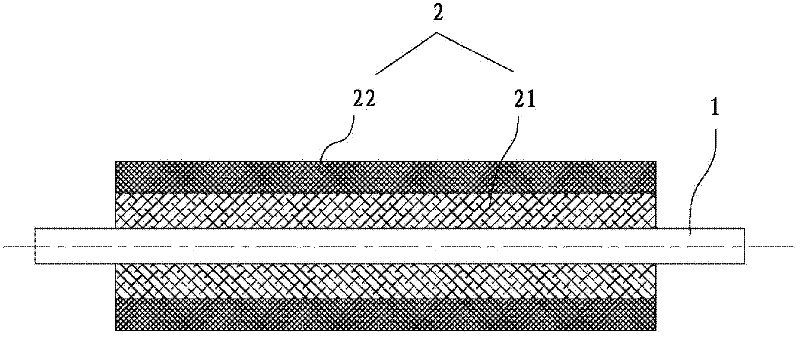
[0033] Then rubber composition I and rubber composition II are molded with a double-pipe extruder according to the standard that the inner layer is rubber mixture I, with a diameter of 16mm, and the outer layer is rubber mixture II, with a diameter of 19mm, and a metal shaft is placed in the midd...
Embodiment 2
[0035] Nitrile rubber [δ C =19.2(J / cm 3 ) 1 / 2 ] 70 parts, epichlorohydrin rubber [δ C =19.8(J / cm 3 ) 1 / 2 ]30 parts, carbon black 20 parts, dioctyl phthalate [δ A =19.58(J / cm 3 ) 1 / 2 ] 45 parts, 40 parts of light calcium carbonate, 2 parts of sulfur, 1 part of vulcanization accelerator, it is mixed uniformly with open type rubber mixing machine or closed type rubber mixing machine according to conventional method, obtains rubber composition I.
[0036] The EPDM rubber ([δ B =16.2(J / cm 3 ) 1 / 2 ] 100 parts, 25 parts of carbon black, 1.5 parts of sulfur, and 1.5 parts of vulcanization accelerator were uniformly mixed in the same manner as above to obtain rubber composition II.
[0037] Then rubber composition I and rubber composition II are molded with a double-pipe extruder according to the standard that the inner layer is rubber mixture I, with a diameter of 16mm, and the outer layer is rubber mixture II, with a diameter of 19mm, and a metal shaft is placed in the midd...
Embodiment 3
[0039] Nitrile rubber [δ C =19.2(J / cm 3 ) 1 / 2 ] 70 parts, epichlorohydrin rubber [δ C =19.8(J / cm 3 ) 1 / 2 ] 30 parts, 20 parts of carbon black, triglyceride (acetyl ricinoleic acid) ester [δ A =19.34 (J / cm 3 ) 1 / 2 ] 45 parts, 40 parts of light calcium carbonate, 2 parts of sulfur, 1 part of vulcanization accelerator, it is mixed uniformly with open type rubber mixing machine or closed type rubber mixing machine according to conventional method, obtains rubber composition I.
[0040] The EPDM rubber ([δ B =16.2(J / cm 3 ) 1 / 2 ] 100 parts, 25 parts of carbon black, 1.5 parts of sulfur, and 1.5 parts of vulcanization accelerator were uniformly mixed in the same manner as above to obtain rubber composition II.
[0041] Then rubber composition I and rubber composition II are molded with a double-pipe extruder according to the standard that the inner layer is rubber mixture I, with a diameter of 16mm, and the outer layer is rubber mixture II, with a diameter of 19mm, and a me...
PUM
| Property | Measurement | Unit |
|---|---|---|
| thickness | aaaaa | aaaaa |
| thickness | aaaaa | aaaaa |
| hardness | aaaaa | aaaaa |
Abstract
Description
Claims
Application Information
 - R&D
- Intellectual Property
- Life Sciences
- Materials
- Tech Scout
- Unparalleled Data Quality
- Higher Quality Content
- 60% Fewer Hallucinations
Browse by: Latest US Patents, China's latest patents, Technical Efficacy Thesaurus, Application Domain, Technology Topic, Popular Technical Reports.
© 2025 PatSnap. All rights reserved.Legal|Privacy policy|Modern Slavery Act Transparency Statement|Sitemap|About US| Contact US: help@patsnap.com