Laser weld-bonding method of bipolar plate of fuel cell

A fuel cell and bipolar plate technology, applied to fuel cell parts, battery electrodes, laser welding equipment, etc., can solve the problems of complex vacuuming process, low production efficiency, high production cost, etc., and achieve poor corrosion resistance, connection The effect of high reliability and high mechanical strength

Active Publication Date: 2012-07-18
SHANGHAI JIAO TONG UNIV +3
View PDF8 Cites 21 Cited by
  • Summary
  • Abstract
  • Description
  • Claims
  • Application Information

AI Technical Summary

Problems solved by technology

The characteristics of this invention are: using laser welding, the weld seam has high strength and corrosion resistance; the assembly is tight and there is no gap, which ensures the stability of laser welding; but the con

Method used


Image

  • Laser weld-bonding method of bipolar plate of fuel cell
  • Laser weld-bonding method of bipolar plate of fuel cell
  • Laser weld-bonding method of bipolar plate of fuel cell

Examples


Embodiment 1

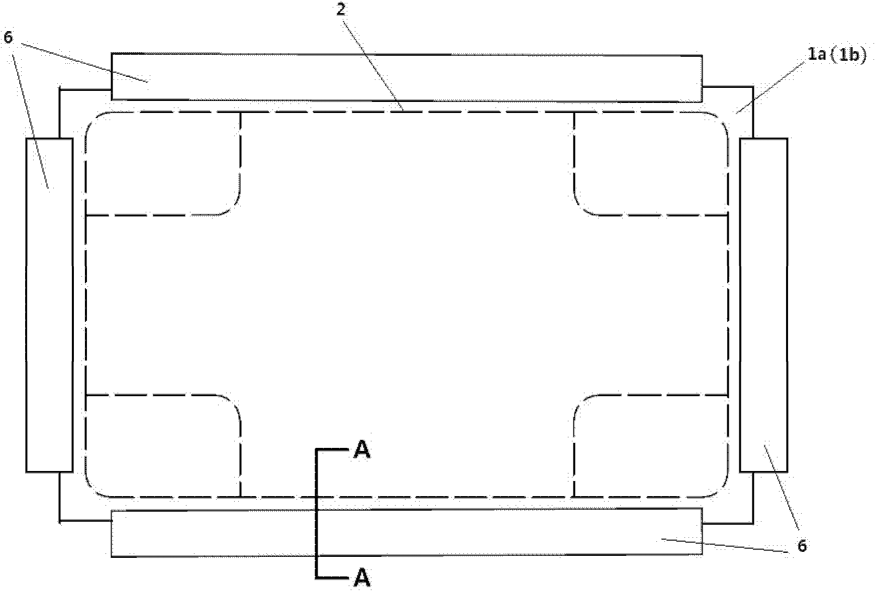
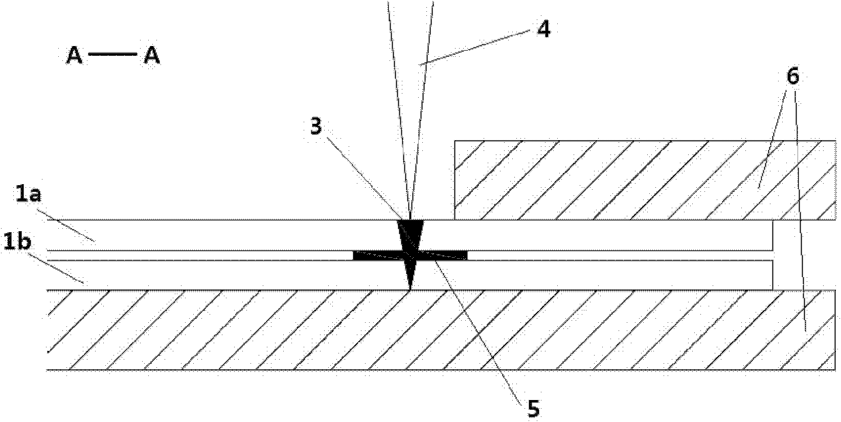
[0027] Such as Figure 1-2 As shown, a fuel cell thin metal bipolar plate includes a metal unipolar plate 1a, a metal unipolar plate 1b, a welding path 2 and a welding joint 3, wherein the welding path 2 is based on the fuel cell metal bipolar plate Sealing requires a designed heat source moving track, and the welded joint 3 is a lapped joint of double-layer metal sheets.

[0028] The specific working process of the laser glue welding method of the thin metal bipolar plate of the fuel cell is as follows: firstly, the normal temperature curing glue is applied to the welding path 2 on the contact surface of the metal unipolar plate 1a and the metal unipolar plate 1b to form a glue layer 5. The width of the adhesive layer 5 is 0.5mm, and the thickness of the adhesive layer is 0.05mm; then, the metal unipolar plate 1a and the metal unipolar plate 1b are positioned and pressed tightly with the welding fixture 6; the heat source 4 is welded by laser welding, and formed at one time. ...

Embodiment 2

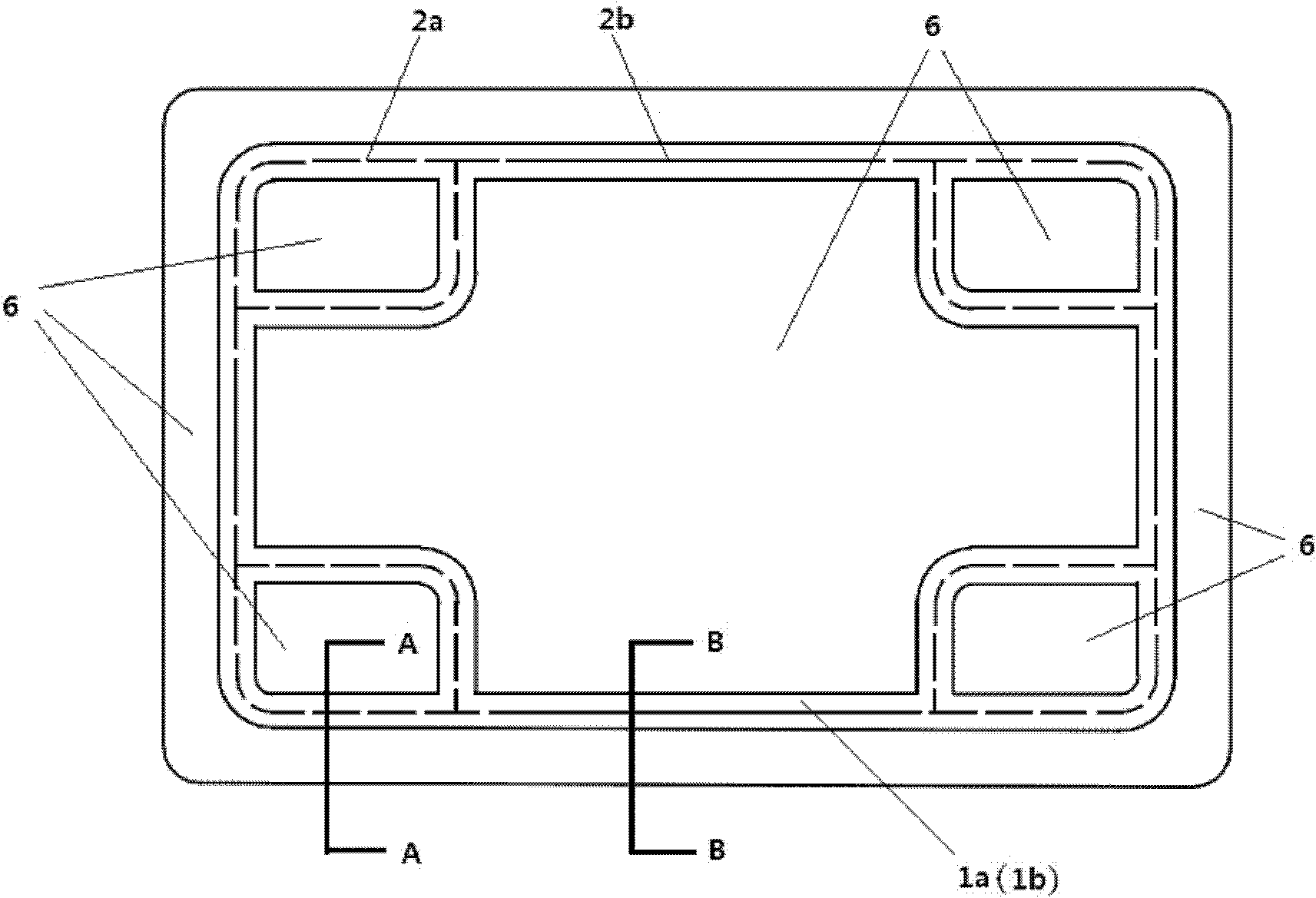
[0032] Such as Figure 3-5 As shown, a fuel cell thin metal bipolar plate includes a metal unipolar plate 1a, a metal unipolar plate 1b, a welding path 2a, a welding path 2b and a welding joint 3, wherein the welding path 2a is based on the fuel cell metal Bipolar plate sealing requires a designed heat source movement track, and glue coating on the welding path. The welding path 2a is often on the welding path, the intersection area of ​​multiple paths, the area where the path turns sharply, the area where the clamping force is unevenly distributed, and the adjacent welding fixture has a worn welding path, but it is not limited to the above areas; Welding path 2b is a heat source movement track designed according to the sealing requirements of fuel cell metal bipolar plates, and the welding path is not coated with glue; welding joint 3 is a lap joint of double-layer metal thin plates.

[0033] The specific working process of the laser glue welding method of the thin metal bip...


PUM


Abstract

The invention relates to a laser weld-bonding method of bipolar plates of a fuel cell. The method combines a bonding process and a laser welding process to connect the bipolar plates of the fuel cell, namely a normal-temperature curing adhesive is used to bond welding areas of the bipolar plates of the fuel cell, and then the laser welding is carried out to finish the connection of the bipolar plates of the fuel cell. Compared with the prior art, the laser weld-bonding method has the advantages that: because an adhesive bonding method is adopted to bond the bipolar plates of the fuel cell tightly, the phenomenas of sealing-off and welding seam breakage caused by assembling gaps in the laser welding are eliminated, the laser welding quality is improved, and the welding seam is high in mechanical strength and is corrosion resistant; a bond layer can evaporate rapidly under the high-heat input of a laser beam, the requirement of the bonding position is reduced; because the normal-temperature curing adhesive is adopted, the secondary heat input caused by high-temperature curing is avoided; and due to the introduction of the bonding process, the designs of a welding clamp, a welding path and welding parameters can be more flexible and simpler, so that the laser weld-bonding method is easy in large-scale production.

Description

technical field [0001] The invention relates to a method for connecting fuel cell bipolar plates, in particular to a laser glue welding method for fuel cell bipolar plates. Background technique [0002] A fuel cell (FC) is a power generation device that uses electrochemical principles to directly convert the chemical energy present in fuel and oxidant into electrical energy. It has the advantages of high energy conversion efficiency, low emission of harmful gas and noise, and high reliability, and is a promising new power generation technology recognized worldwide. In addition to the advantages of general fuel cells, proton exchange membrane fuel cells (PEMFC) also have the advantages of low operating temperature, fast start-up, high specific power, simple structure, convenient operation, and suitable for product miniaturization, etc. focus of attention. [0003] The structure of a proton exchange membrane fuel cell mainly includes a bipolar plate, a proton exchange membra...

Claims


Application Information

Patent Timeline
IPC IPC(8): B23K26/20B23K26/42H01M8/02B23K26/211H01M4/88H01M8/0202
CPCY02E60/50Y02P70/50
Inventor 彭林法胡唯张延松黄晨东方亮
Owner SHANGHAI JIAO TONG UNIV
Why Eureka
Try Eureka