
H full-bridge conversion type micro-inverter grid connecting device

An inverter and full-bridge circuit technology, applied in the field of H full-bridge conversion micro-inverter grid-connected devices, can solve the problems of expensive transformers, reduced solar power generation, bulky volume, etc., and achieve simple control circuits and drive circuits, and Reduces complexity and cost, reduces power components effectiveness

Inactive Publication Date: 2012-07-18
JIANGSU XIANGHE ELECTRONICS SCI & TECH
View PDF8 Cites 20 Cited by
  • Summary
  • Abstract
  • Description
  • Claims
  • Application Information

AI Technical Summary

Problems solved by technology

As a result, only 10% shading of a solar PV system can halve solar power generation
The reason for this phenomenon is that the current photovoltaic system structure is unreasonable, and its system structure affects the reliability, cost and efficiency of the inverter
The reason is that the cascade confluence inverter method of multiple photovoltaic panels causes some solar photovoltaic panels to fail, which will affect the entire photovoltaic power generation system.
On the basis of not using the above-mentioned photovoltaic power generation structure, one way of the current general-purpose inverter device is to first invert to low-voltage AC power, and then transform the voltage to meet the grid-connected AC power through an automatically adjustable power frequency transformer. This method has high requirements on the transformer, and the transformer is expensive and bulky for the user. Although the inverter circuit is simplified, the economy and reliability are poor; another common method is to go through the DC / DC boost circuit first, First boost the voltage to a certain range, and then convert it into a power-frequency alternating current that meets the grid-connected requirements.
Adopting the universal high reliability and stability DC / DC method to design the entire solar inverter grid-connected device needs to use more full-control switch tubes and power diodes, which is costly, complicated to control, and difficult to maintain the system

Method used


Image

  • H full-bridge conversion type micro-inverter grid connecting device
  • H full-bridge conversion type micro-inverter grid connecting device
  • H full-bridge conversion type micro-inverter grid connecting device

Examples


Embodiment Construction

[0029] The content of the present invention will be further described below in conjunction with the accompanying drawings.

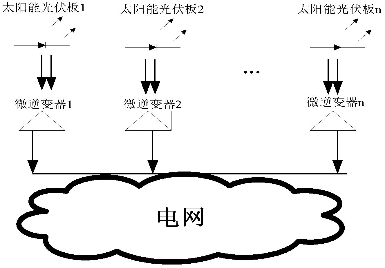
[0030] An embodiment of the present invention provides a novel micro-inverter circuit topology, wherein the inverter used is a micro-inverter with wide voltage input and miniaturized inverting power, for example, at 230W In the device, its input voltage can be boosted to a voltage value that meets the grid-connected requirements within the range of 28V ~ 36V, thereby expanding the range of input voltage. Install the above-mentioned micro-inverter on each or several panels, and connect solar photovoltaic panels in a distributed manner, such as figure 1 As shown, this distributed structure can substantially improve the cost-effectiveness and efficiency of solar power generation.

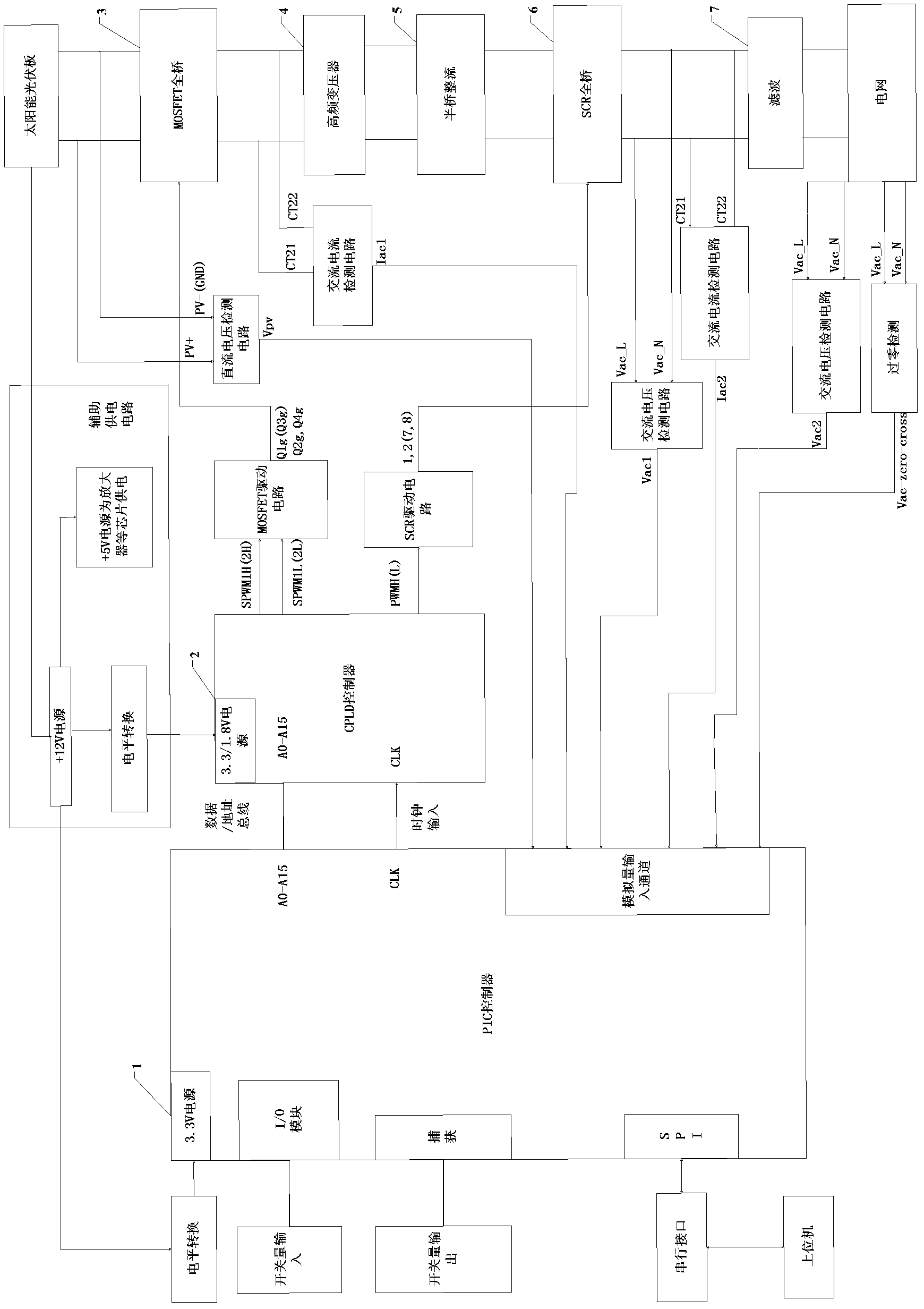
[0031] figure 2It is a structural block diagram of a H full-bridge conversion type micro-inverter grid-connected device in an embodiment of the present invention, including a ...


PUM


Abstract

An H full-bridge conversion type micro-inverter grid connecting device belongs to the technical field of electrical engineering and resolves the problem of the decreasing efficiency of the whole photovoltaic plate group caused when a fault of any photovoltaic plate in prior solar photovoltaic system cascades occurs. The H full-bridge conversion type micro-inverter grid connecting device comprises a single-chip microcomputer controller, a complex programmable logic device (CPLD) controller, a metal-oxide-semiconductor field effect transistor (MOSFET) full-bridge circuit, a high-frequency transformer, a half-bridge rectification circuit, a silicon controlled rectifier (SCR) full-bridge circuit and a filter circuit. According to the H full-bridge conversion type micro-inverter grid connecting device, a MOSFET tube bridge is in full-bridge type, the transformer is a single-phase transformer with a center tap and a SCR bridge circuit, by means of the integral structure, the quantity of elements is reduced, the requirement on power switch tubes is reduced, a control circuit and a driving circuit are enabled to be simple, and accordingly, the purposes of reducing the quantity of full-control switch components, improving the system reliability and decreasing the system cost are achieved.

Description

technical field [0001] The invention belongs to the technical field of electrical engineering, and in particular relates to an H full-bridge conversion type micro-inverter grid-connected device. Background technique [0002] The current general-purpose inverter grid-connected devices are all high-power, requiring more photovoltaic panels to be grouped and connected in series first, and then different series-connected battery groups are connected in parallel to form a photovoltaic array. The DC power generated by the solar panel array is funneled to an inverter located next to the panels. In this type of photovoltaic system, solar panels are formed by connecting multiple series groups in parallel. Just like holiday lights, if any one cell in the series fails, it can cause the entire pack to fail. In addition, this can also occur when there is partial shading or debris, etc. shades the PV system. As a result, it takes only 10% shading of a solar photovoltaic system to cut s...

Claims


Application Information

Patent Timeline
Patent Type & Authority Applications(China)
IPC IPC(8): H02J3/38H02M3/335H02M7/515H02M1/12H02H7/20
CPCH02M1/12H02J3/38H02M7/515H02M3/33569Y02B70/1475H02M7/4807Y02E10/56H02H7/20Y02E10/563H02M2001/007H02M3/335H02M1/007H02M3/33573
Inventor 杨东升张化光张光儒汪刚焦阳李乐刘鑫蕊王迎春王日江
Owner JIANGSU XIANGHE ELECTRONICS SCI & TECH
Learn More