Pneumatic conveying device for conveying laminar materials

A pneumatic conveying, sheet-like technology, applied in conveying bulk materials, conveyors, transportation and packaging, etc., which can solve the problems of difficult cutting, unsuitable for large-scale industrial production, and environmental pollution.

Inactive Publication Date: 2012-07-25
BEIJING JINYU MANGROVE ENVIRONMENTAL PROTECTION TECH
View PDF5 Cites 7 Cited by
  • Summary
  • Abstract
  • Description
  • Claims
  • Application Information

AI Technical Summary

Problems solved by technology

[0004] At present, there have been test reports on crushing FRP waste into powders with a particle size of 10 mm and sending them into cement kilns for combustion. In this test, the crushed particle size of FRP is small, resulting in high crushing costs, which is not suitable for large-scale industrial production.
In the actual production process, the FRP material can be crushed to a particle size of 20mm in order to control the cost, but unlike the general powder material, the flake material with a particle size of 20mm has light weight, uneven density, poor fluidity, and prone to bridging. Problems such as difficulty in cutting materials
[0005] The traditional wind conveying system in the known technology can only convey powdery materials with smaller particle sizes, and bridging phenomenon is prone to occur when conveying flake materials; while the belt conveying system cannot achieve uniform distribution, and is prone to failure when conveying light materials. Spilling and scattering of materials will pollute the surrounding environment
Therefore, the known belt conveying and wind conveying methods are not suitable for conveying flake-shaped alternative fuels with a particle size of more than 10mm prepared by FRP composite materials.

Method used


Image

  • Pneumatic conveying device for conveying laminar materials
  • Pneumatic conveying device for conveying laminar materials
  • Pneumatic conveying device for conveying laminar materials

Examples


Embodiment Construction

[0032] The pneumatic conveying device for transporting flake materials provided by the invention solves the problem that flake materials such as glass fiber reinforced plastics which replace fuel are difficult to convey.

[0033] The present invention will be described in detail below in conjunction with the accompanying drawings.

[0034] Metering lock air feeding system:

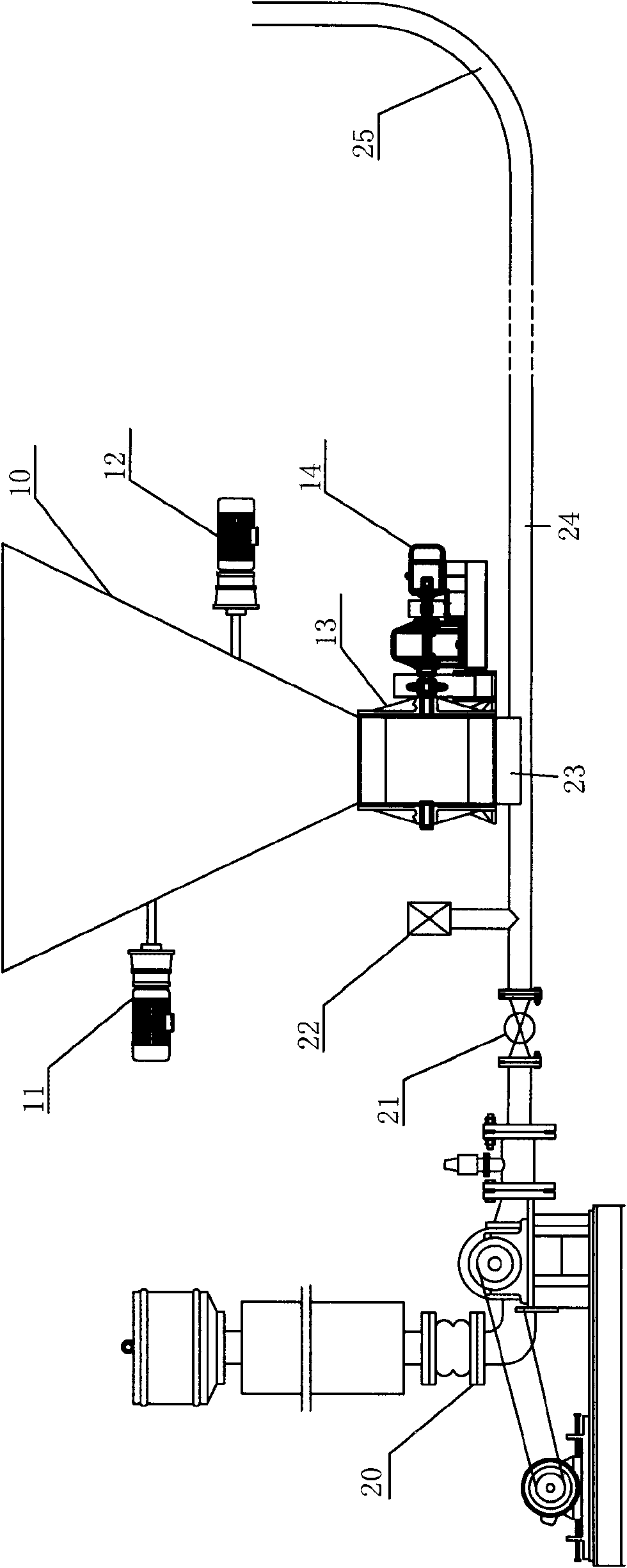
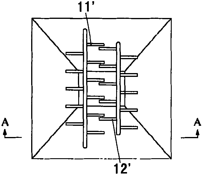
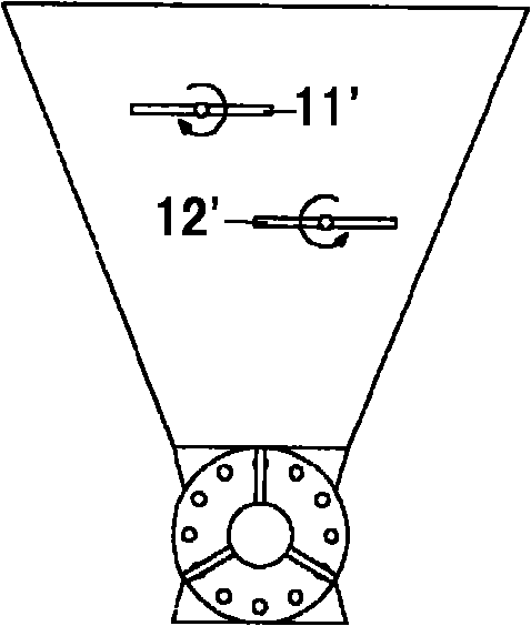
[0035] The metering lock air feeding part is composed of the following parts: buffer feeding bin 10, two-stage feeding device 11, 12, rotary feeding device 13, motor and reducer matched with feeding device and rotary feeding device 14.

[0036] The crushed flake materials with an average particle size of less than 20 mm first enter the buffer lower hopper, which is in the shape of an inverted square. Because the broken glass fiber reinforced plastics are prone to sticking and cause material bridging, there is a corrugated liner (not shown in the figure) inside the buffer lower silo. The form of the liner...


PUM


Abstract

The invention discloses a pneumatic conveying device for conveying laminar materials, which is mainly composed of a metering, air locking and blanking part and a part of conveying air into a kiln; the metering, air locking and blanking part comprises a buffer blanking bin, wherein the lower port of the buffer blanking bin is connected with a rotary blanking device; two kick-out devices arranged up and down are transversely arranged in the buffer blanking bin, and the axle centers of the two kick-out devices are respectively situated at the two sides of a central line in the buffer blanking bin; and comb-shaped material kick-out teeth are arranged on a rotating shaft of the kick-out device, and the comb-shaped material kicking teeth are staggered with each other. The part of conveying air into the kiln comprises a roots blower connected with an air conveying pipeline; the rotary blanking device of the metering, air locking and blanking part is connected with the air conveying pipeline through a blanking chute; and the other end of the air conveying pipeline is connected with a multi-passage combustor of a cement kiln precombustion furnace or a cement kiln front. The pneumatic conveying device for conveying laminar materials, disclosed by the invention, can effectively convey glass fiber reinforced plastic composite materials serving as cement to replace fuel.

Description

technical field [0001] The invention relates to a pneumatic conveying device, in particular to a pneumatic conveying device for conveying sheet objects. Background technique [0002] Fiberglass reinforced plastic (FRP) products are synthetic composite materials consisting of fiber polymers encapsulated in a polymer matrix. The reinforcement material used is usually glass fiber, but aramid fiber (Kevlar) or carbon fiber can also be used as reinforcement material, which is widely used in various industries due to its light weight, high strength, and corrosion resistance. . Generally, the service life of FRP products is about 10-15 years. After long-term use, the FRP materials used in the early stage are gradually eliminated and turned into solid waste. Use is increasing year by year. Because FRP composites are thermosetting and contain a large amount of glass fibers, the waste treatment process of FRP composites is very difficult, and the problem of waste disposal and recyc...

Claims


Application Information

Patent Timeline
IPC IPC(8): B65G53/04B65G53/40B65G53/48B65G53/52B65G53/36B65D88/64B65D88/68F23K3/02
Inventor 蔡金山姜雨生贾春立刘超刘佳
Owner BEIJING JINYU MANGROVE ENVIRONMENTAL PROTECTION TECH
Why Eureka
Try Eureka