
Gas fractionation method

A technology of gas fractionation and condenser, applied in the direction of distillation purification/separation, organic chemistry, etc., can solve the problems of increased floor area and operating costs, waste, unusable heat sources, etc., to reduce equipment investment, design pressure reduction, cooling The effect of load reduction

Active Publication Date: 2012-07-25
CHINA PETROCHEMICAL CORP +1
View PDF5 Cites 11 Cited by
  • Summary
  • Abstract
  • Description
  • Claims
  • Application Information

AI Technical Summary

Problems solved by technology

If it is necessary to expand the capacity of the existing device, such as when the processing capacity is increased by 50%, it is necessary to increase the diameter of each tower or add a new tower to operate in parallel with the original tower, which will increase the floor space and operating costs; if To expand the capacity of the new plant, the propylene tower needs to be operated in series with two towers
In addition, using the existing conventional fractionation method, the temperature of the low-temperature heat source required by the gas fractionation device is not less than 90°C, and the heat source at a lower temperature in the whole plant cannot be used, resulting in waste

Method used


Image

  • Gas fractionation method
  • Gas fractionation method
  • Gas fractionation method

Examples


Embodiment 1

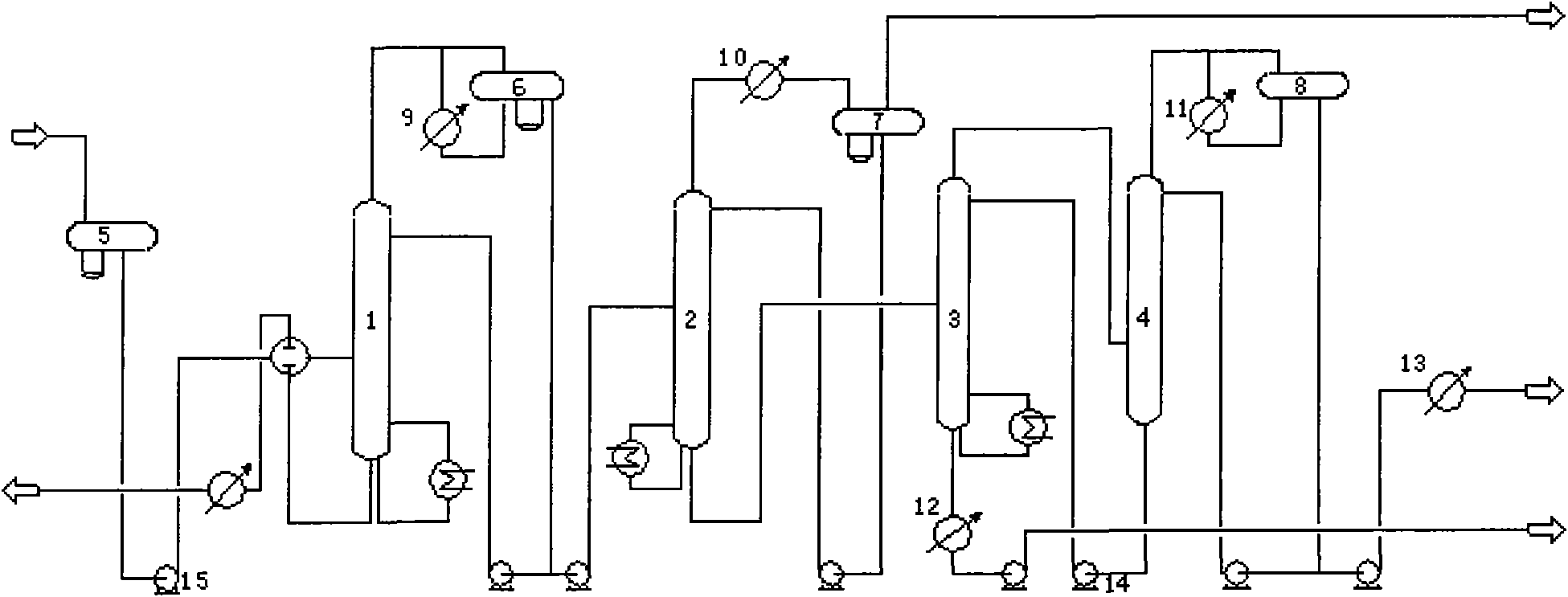
[0038] Such as figure 1 As shown, when the original device is transformed, it is only necessary to change the tubes of the depropanizer overhead condenser 9, deethanizer overhead condenser 10, and propylene overhead condenser 11 from circulating water to chilled water at 5-10°C , if the original top of the tower is condensed and cooled to an air cooler, the air cooler needs to be changed to a shell-and-tube or plate condenser. The pressure is 1.5-1.8MPa, the gauge pressure at the top of the second propylene tower 4 is 0.8-1.1MPa, the feed pump 15 of the device is modified or replaced, the head of the pump is 160 meters, the diameter of each tower remains unchanged, and the process flow is the same as that without modification The processing flow of the device can be increased by 50% without changing the internal components of the tower.

Embodiment 2

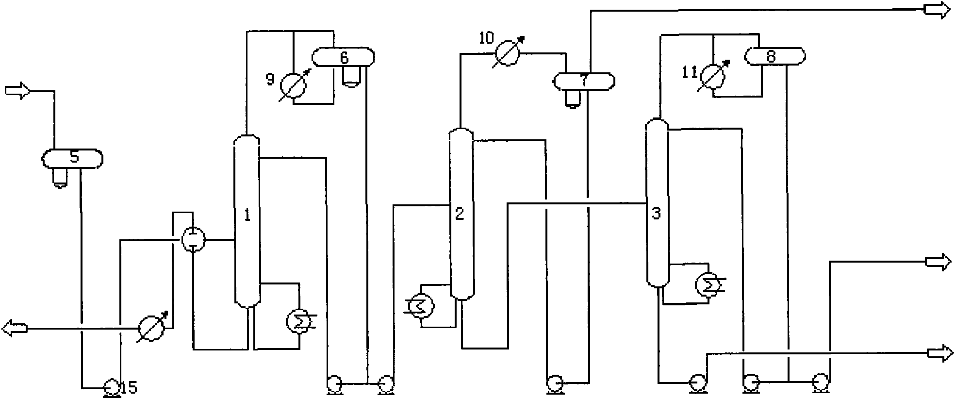
[0040] Such as figure 2 As shown, if the device is newly built and adopts the chilled water process, the number of propylene tower trays can be reduced from 200 to 130 layers, and only one propylene tower can be used, and the skirt of each tower is lowered by 2 meters. The design pressure is reduced.

[0041] as attached figure 2As shown, after the raw material liquefied gas after desulfurization passes through the raw material buffer tank 5, it is sent into the depropanizer 1 with the device feed pump 15, and the pressure at the top of the depropanizer 1 is controlled at 0.8 to 1.1 MPa. The C3 fraction enters the depropanizer top reflux tank 6 after being condensed by the depropanizer top condenser 9, a part of the liquid is used as the reflux of the depropanizer tower, and the other part is sent into the deethanizer tower 2 through the deethanizer feed pump, and the bottom of the tower is The C4 fraction is cooled by heat exchange and then exits the device; the pressure ...


PUM


Abstract

The invention relates to a gas fractionation method. Raw materials for gas fractionation are refinery liquefied gas. Products mainly comprise chemical grade or polymer grade propylene. The method comprises the steps of: using a rich low-temperature heat source of a refinery to prepare chilled water, using the chilled water for condensation cooling at the top of a tower and reducing the operating pressure and the backflow amount of the tower at the same time to conduct gas fractionation. With respect to the existing device, after the pressure is reduced, under the conditions that the number of tower plates is equal to the number of tower plates used in a conventional fractionation method and the device flow process and the equipment are basically unchanged, the treatment amount of each tower can be increased by 50 percent. For newly built device, dual-tower serial-connection operation of a propylene tower in the original conventional fractionation method is changed to be single-tower operation, a tower and a propylene tower intermediate pump are reduced and the flow process is simplified; and besides, the design pressure of each tower can be reduced and the investment is decreased.

Description

technical field [0001] The invention relates to a process for separating light hydrocarbons in the petrochemical industry, in particular to the separation of liquefied gas in a refinery, that is, a method for separating mixed liquefied gas into individual components or fractions by fractional distillation. Background technique [0002] At present, domestic and foreign refineries use conventional processes or heat pump technology to separate propylene from liquefied gas. The main components of the process are depropanizer, deethanizer, and propylene tower. The propylene tower is divided into two types due to the large number of plates The two towers are operated in series. In the conventional process, the operating pressure of each tower is generally controlled as follows: the gauge pressure of the depropanizer tower is 1.7~1.9MPa, the pressure gauge pressure of the deethanizer tower is 2.7~2.9MPa, and the pressure gauge pressure of the propylene tower is 1.7~ 1.9MPa. [000...

Claims


Application Information

Patent Timeline
IPC IPC(8): C07C11/06C07C7/04
Inventor 张立新宁波郭志雄黄少敏
Owner CHINA PETROCHEMICAL CORP
Learn More