Flue-gas waste-heat recycling system

A flue gas waste heat recovery system technology, which is applied to heat exchanger shells, indirect heat exchangers, heat exchange equipment, etc. Overhaul and maintenance, easy operation and management, easy disassembly effect

Active Publication Date: 2014-03-12
北京新世翼节能环保科技股份有限公司
View PDF4 Cites 2 Cited by
  • Summary
  • Abstract
  • Description
  • Claims
  • Application Information

AI Technical Summary

Problems solved by technology

[0008] The purpose of the present invention is to provide a new flue gas waste heat recovery system to solve the problem that the refrigerant in the heat exchange tube in the traditional tail gas waste heat recovery system is easily polluted by flue gas, thus affecting the use of the final waste heat utilization device problems; and solve the technical problems of unreasonable structure and inconvenient maintenance of the flue gas heat exchanger in the traditional tail gas waste heat recovery system; and solve the easy damage and heat transfer efficiency of the flue gas heat exchanger in the traditional tail gas waste heat recovery system Technical issues that are prone to deterioration

Method used


Image

  • Flue-gas waste-heat recycling system
  • Flue-gas waste-heat recycling system
  • Flue-gas waste-heat recycling system

Examples


Embodiment Construction

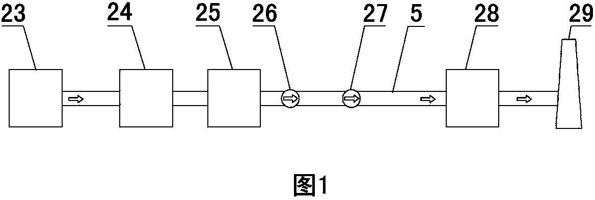
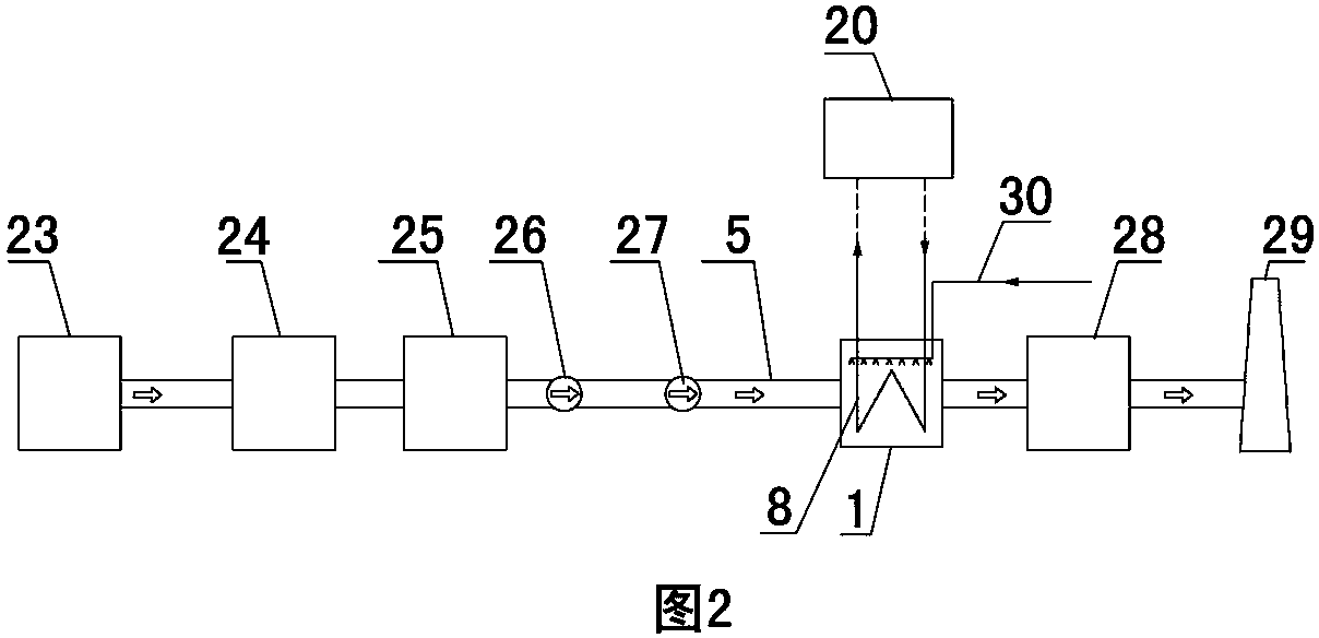
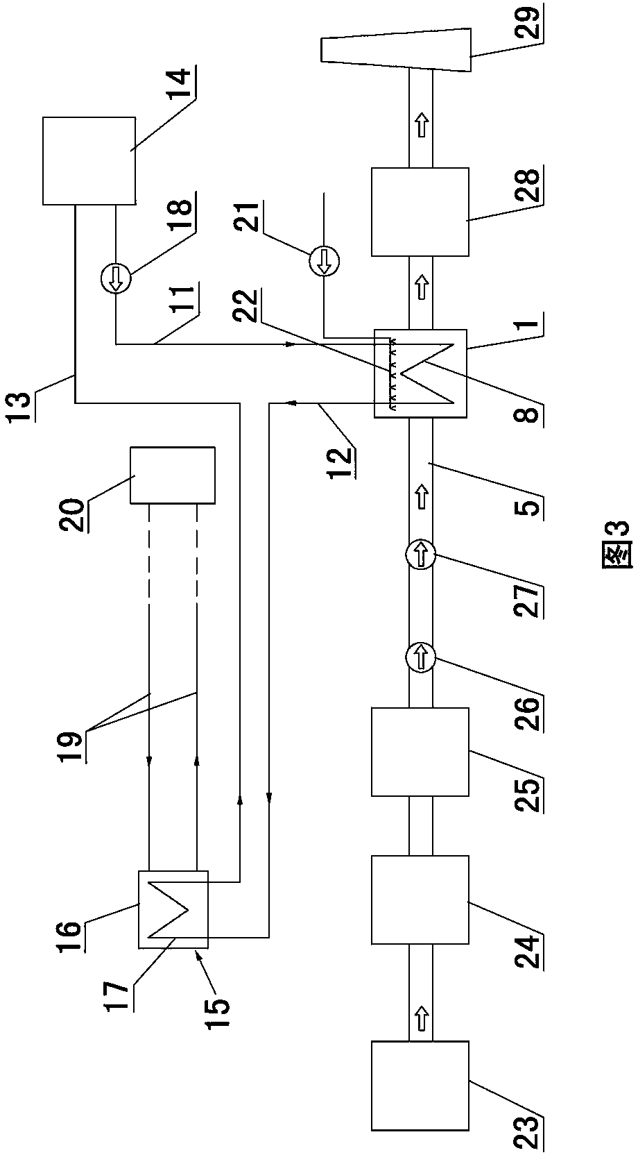
[0040] Examples are shown in Figures 3 and 4. This new type of flue gas waste heat recovery system can be arranged between the outlet of the boiler air preheater and the wet flue gas desulfurization tower (air preheater, dust collector, induced draft fan, booster fan, Wet flue gas desulfurization tower) between any two equipment, or between any two equipment at the same time, the setting position is determined according to the specific needs of users. In this embodiment, it is arranged between the booster fan and the wet flue gas desulfurization tower. When the present invention is arranged at this position, because the wet flue gas desulfurization tower itself has strong anti-corrosion ability, even if the present invention can remove the flue gas The temperature drops below the acid dew point, so the acidic substances in the flue gas after cooling will not cause corrosion hazards to the desulfurization tower. When the present invention is arranged downstream of the outlet of ...


PUM

PropertyMeasurementUnit
widthaaaaaaaaaa
widthaaaaaaaaaa

Abstract

A novel flue-gas waste-heat recycling system comprises a flue-gas heat exchanger, a water inlet pipe, a water outlet pipe, a water tank, a refrigerant medium water pump and a waste-heat using device and further comprises a secondary heat exchanger. The secondary heat exchanger further comprises a secondary heat exchanger casing and a secondary heat exchanger pipe arranged in the secondary heat exchanger casing. The flue-gas heat exchanger is a module type fluorine plastic pipe flue-gas heat exchanger, and positioning meshes are parallelly distributed in a flue-gas heat exchanger casing of the flue-gas heat exchanger at intervals from top to bottom. The novel flue-gas waste-heat recycling system avoids pollution of a finally-heated medium, and the using of the final waste-heat using device is not influenced. The flue-gas heat exchanger is the module type fluorine plastic pipe flue-gas heat exchanger, and accordingly the flue-gas heat exchanger is easy to operate and manage. The positioning meshes are arranged in the module type fluorine plastic pipe flue-gas heat exchanger, and shaking and deformation of a flexible fluorine plastic heat exchange pipe bundle under the flowing impact of flue gas can be avoided.

Description

Technical field [0001] The invention relates to a system for recovering flue gas discharged from boilers in thermal power plants or exhaust heat from other industrial boilers. Background technique [0002] Figure 1 is a schematic diagram of the conventional emission process of boiler flue gas. After the boiler outlet flue gas passes through the air preheater, dust collector, induced draft fan, and booster fan, it enters the wet flue gas desulfurization tower, and then is discharged into the atmosphere through the chimney. Because it works in an acidic corrosive environment, wet flue gas desulfurization towers generally have strong anti-corrosion capabilities. The sulfur dioxide (SO2) contained in the high temperature flue gas in the wet flue gas desulfurization tower 2 ), after the desulfurization reaction of the slurry of sulfur dioxide, limestone (calcium carbonate) and water, solid gypsum (via calcium sulfate dihydrate) and gaseous carbon dioxide are separated, due to the temp...

Claims


Application Information

Patent Timeline
Patent Type & Authority Patents(China)
IPC IPC(8): F28D19/00F28D7/06F28F21/06F28F9/26F28G9/00
CPCY02P80/15
Inventor 赵禹吴敌史大维
Owner 北京新世翼节能环保科技股份有限公司
Why Eureka
Try Eureka