Method and device for rapid high-temperature heating of plates

A high-temperature heating and heating method technology, which is applied in the direction of measuring devices, heat treatment furnaces, and analytical materials, can solve the problems that the heating furnace occupies a large space, cannot reach a high temperature above 900°C, and is easy to be oxidized, and achieves a compact structure of the device. Easy to make, stable and reliable effect

Inactive Publication Date: 2012-08-01
BAOSHAN IRON & STEEL CO LTD
View PDF10 Cites 9 Cited by
  • Summary
  • Abstract
  • Description
  • Claims
  • Application Information

AI Technical Summary

Problems solved by technology

The heating furnace takes up a lot of space and the temperature rises slowly. After the furnace door is opened to take the sample, the furnace temperature drops rapidly, which cannot guarantee the rapid temperature rise of the sample; the resistance heating speed is fast, but the two ends of the sample need conductive clamps. It is convenient to take out the sample, and the temperature of the whole sample is not uniform, forming a temperature gradient that is high in the middle and low at both ends; induction heating has a better heating effect on round rod-shaped materials, and for metal plates with a thickness of less than 5mm, due to its large surface area, it can When exposed to air heating, the heat dissipation is fast, it cannot reach a high temperature above 900°C, and it is easily oxidized. In addition, due to the skin effect of induction heating, the induction heating of the plate often results in uneven temperature of the plate due to the uneven distribution of the induced current , or even local melting of the plate

Method used


Image

  • Method and device for rapid high-temperature heating of plates
  • Method and device for rapid high-temperature heating of plates
  • Method and device for rapid high-temperature heating of plates

Examples


Embodiment 1

[0031] Such as Figure 5a , as shown in 5b and 5c, bend the induction coil 5 into a rectangular frame of 220*220*50mm to ensure the uniformity of heating, a total of 30 turns, and the specific parameters are shown in Table 1.

[0032] Table 1 Induction coil parameter list

[0033]

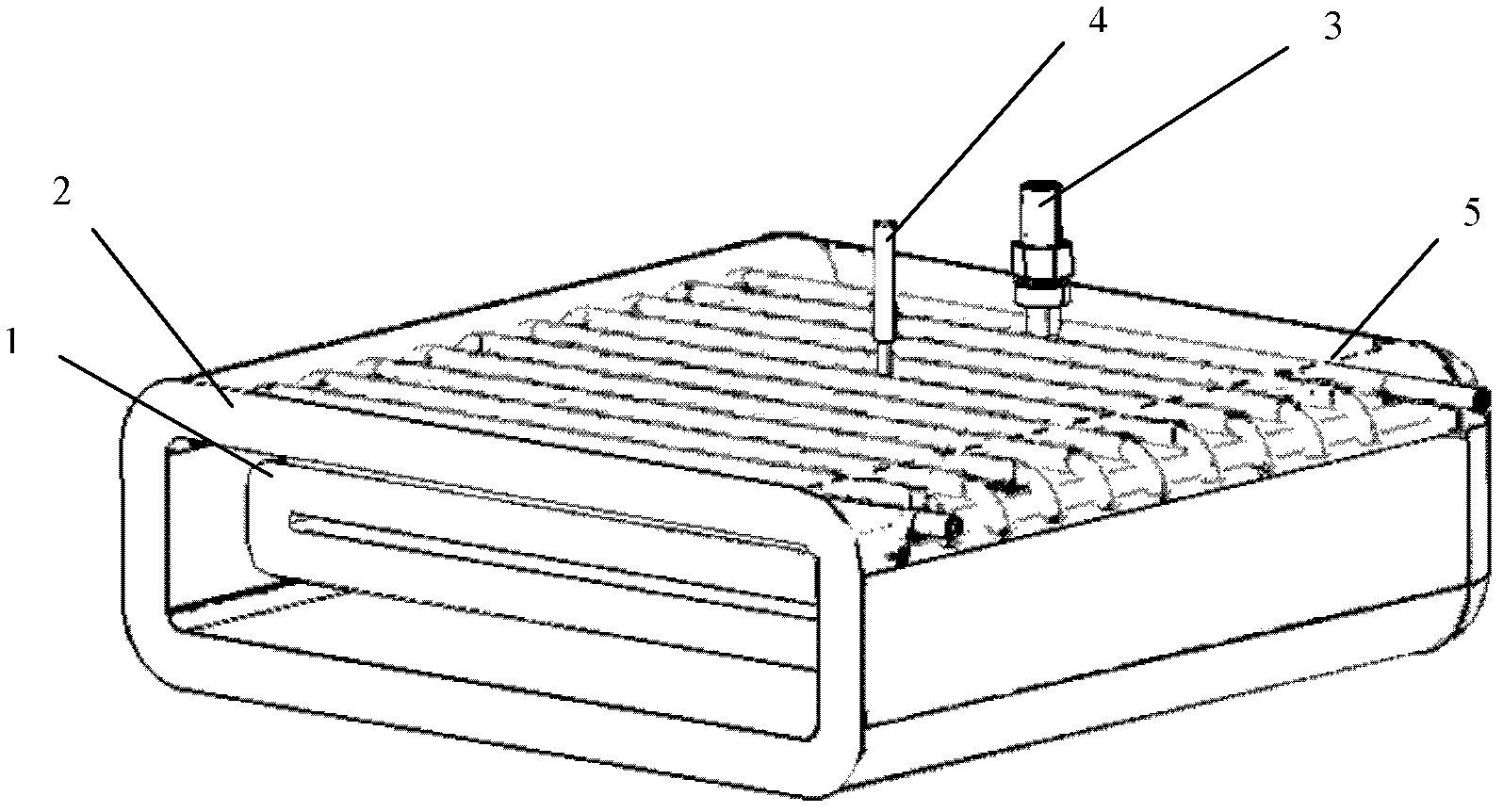
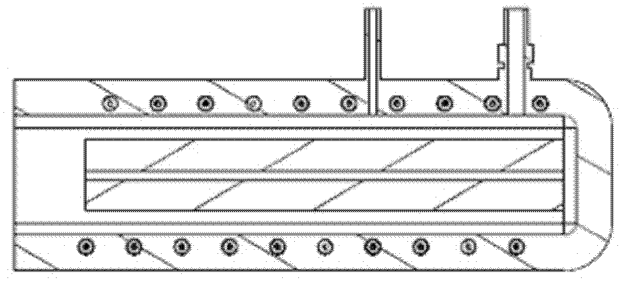
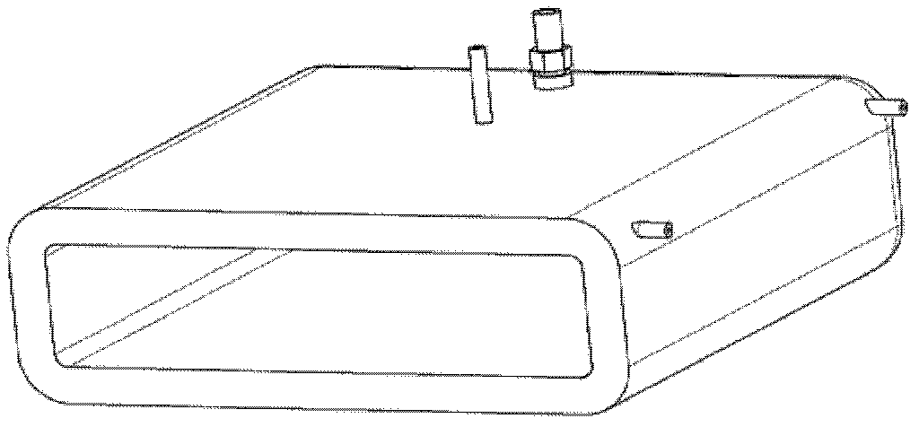
[0034] Such as Figure 1-4 As shown, the induction coil 5 bent into a rectangular frame is fixed and packaged with cement to form a box-shaped heating chamber with one side open, and the positions required for the installation of the protective gas charging port 3 and the thermocouple installation hole 4 are fixed. After the cement is cured , that is, the cement heating chamber 2 is formed. The graphite inner cavity 1 is placed in the center of the cement heating cavity 2, and a gap of 3 mm is left, which is fixed with cement slurry.

[0035] Pass the inert gas helium into the protective gas filling hole 3, drive away the air in the cement heating chamber 2, and prevent the sample from being ...

Embodiment 2

[0037] Such as Figure 5a , 5b, 5c, the induction coil 5 is bent into a rectangular frame of 500mm*500mm*80mm to ensure the uniformity of heating, a total of 80 turns.

[0038] Such as Figure 1-4 As shown, the induction coil 5 bent into a rectangular frame is fixed and packaged with cement to form a box-shaped heating chamber with one side open, and the positions required for the installation of the protective gas charging port 3 and the thermocouple installation hole 4 are fixed. After the cement is cured , that is, the cement heating chamber 2 is formed. The graphite inner cavity 1 is placed in the center of the cement heating cavity 2, and a gap of 8mm is left, and is fixed with cement slurry.

[0039]Pass the inert gas helium into the protective gas filling hole 3, drive away the air in the cement heating chamber 2, and prevent the sample from being over-oxidized at high temperature. Install it in the thermal couple installation hole 4, and connect the thermostat; conn...

Embodiment 3

[0041] Such as Figure 5a , As shown in 5b and 5c, the induction coil 5 is bent into a rectangular frame of 400mm*400mm*65mm to ensure the uniformity of heating, with a total of 60 turns.

[0042] Such as Figure 1-4 As shown, the induction coil 5 bent into a rectangular frame is fixed and packaged with cement to form a box-shaped heating chamber with one side open, and the positions required for the installation of the protective gas charging port 3 and the thermocouple installation hole 4 are fixed. After the cement is cured , that is, the cement heating chamber 2 is formed. The graphite inner cavity 1 is placed in the center of the cement heating cavity 2, and a gap of 5mm is left, and is fixed with cement slurry.

[0043] Pass the inert gas helium into the protective gas filling hole 3, drive away the air in the cement heating chamber 2, and prevent the sample from being over-oxidized at high temperature. Install it in the thermal couple installation hole 4, and connect...


PUM


Abstract

Disclosed are a method and a device of rapid high-temperature heating of plates. The method includes: filling a cement heating chamber with inert gas, starting an induction heating power supply to heat an inner graphite chamber to a certain degree, putting a metal sample plate in a gap of the inner graphite chamber, heating the metal sample plate to the set temperature, keeping the plate at the temperature, using a thermocouple to monitor the temperature of graphite in the heating chamber in real time during heating, and using a thermostat to control heating power of an induction coil. By means of closed-loop control with feedback, stable and controllable heating is guaranteed. In addition, water is filled into hollow copper tubes during heating to cool the induction coil, so that the coil is protected from damage by high heat. By the method and the device, the plates are heated evenly and successfully, the plates are quickly heated to the ultrahigh temperature up to 950 DEG C, and the samples are protected from over-oxidation. The device is compact in structure, easy and convenient in manufacture, small in occupied space, energy-saving, environment-friendly, fast in heating temperature control, and stable and reliable in operation.

Description

technical field [0001] The invention relates to a method and a device capable of rapid high-temperature heating of a plate, in particular to a method and a device for heating a steel high-temperature forming limit test sample for hot stamping. Background technique [0002] Hot stamping is a new forming technology developed in the past 20 years. Its technological feature is to heat the Boron steel plate with an original strength of about 400-600Mpa to the austenitic temperature range, move it to the mold quickly and stamp it quickly, and keep it in the press. In the pressed state, the parts are rapidly cooled through the mold to achieve quenching and strengthening, and a martensitic structure and a tensile strength of about 1500Mpa or even higher are obtained. The use of hot stamping parts in the body structure can greatly improve the collision safety of the body, reduce the weight of the body, and meet the requirements of the automotive industry for safety, energy saving, en...

Claims


Application Information

Patent Timeline
Patent Type & Authority Applications(China)
IPC IPC(8): C21D1/42C21D9/52G01N3/60
CPCY02P10/25
Inventor 洪振军徐伟力罗爱辉艾健吴彦骏俞宁峰
Owner BAOSHAN IRON & STEEL CO LTD
Why Eureka
Try Eureka