Multi-functional large-sized metal surface treating machine

A metal surface treatment machine technology, which is applied in metal processing equipment, used abrasive treatment devices, abrasive jetting machine tools, etc., can solve the problem of equipment size and maneuverability, the shot blasting head cannot be flexibly adjusted, and the impact Surface treatment efficiency and quality issues, to achieve the effect of reliable long-term automatic operation, excellent treatment quality, and improved mobility and flexibility

Inactive Publication Date: 2012-08-15
WUXI ZHONGYING INDAL
View PDF7 Cites 3 Cited by
  • Summary
  • Abstract
  • Description
  • Claims
  • Application Information

AI Technical Summary

Problems solved by technology

[0004] As disclosed in the latter patent, the shot blasting machine adopts a double chain and feeding hopper structure to realize the recovery and feeding of steel shots, but this structure is large in size, complex in internal structure, and heavy in weight. It is used as a fixed device. It may not be a big problem, but on the motorized equipment that needs to be moved and lifted flexibly, the heavy working head part needs to be equipped with a very strong support arm at the rear, which directly affects the size and maneuverability of the entire equipment; and the chain work The noise of pouring steel balls from the feeding hopper is very loud, and the working environment is very noisy
The feeding hopper is used for feeding, and the feeding is intermittent and discontinuous, so the steel shots shot by the shot blasting head are also intermittent, which seriously affects the efficiency and quality of surface treatment.
[0005] In addition, the shot blasting machine disclosed in this patent has increased the bottom walking base and the double four-link type two-dimensional mobile support arm, so that the range of up and down movement can reach 2.5 meters, but for some special processing occasions, such as very high Oil and gas storage tanks, this equipment cannot meet the requirements, and the shot blasting head of this equipment cannot be adjusted flexibly, so it cannot effectively treat the inclined vertical surface of the hull surface of large ships

Method used


Image

  • Multi-functional large-sized metal surface treating machine
  • Multi-functional large-sized metal surface treating machine
  • Multi-functional large-sized metal surface treating machine

Examples


Embodiment Construction

[0035] The specific implementation manner of the present invention will be described below in conjunction with the accompanying drawings.

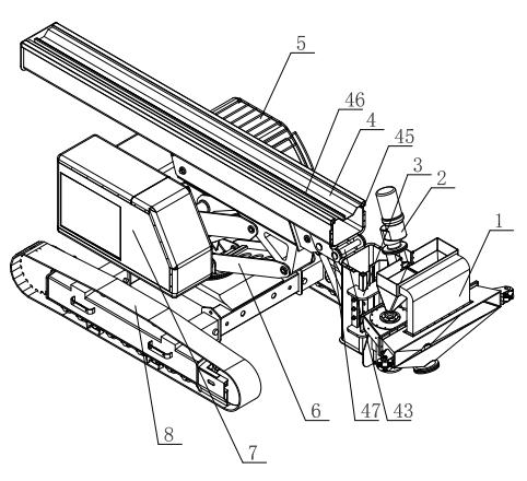
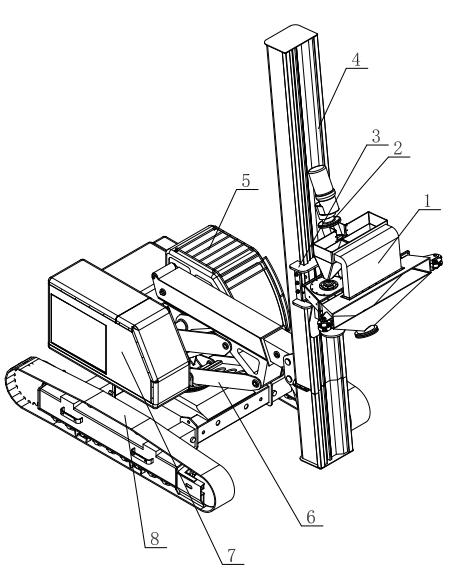
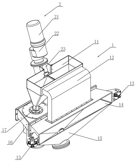
[0036] Such asfigure 1 , figure 2 As shown, the base 61 of the parallelogram linkage mechanism 6 of the support arm structure of the present invention is installed on the mobile platform 8 through a rotary pair, and a dust removal box 5 and a control room 7 are arranged on both sides of the parallelogram linkage mechanism 6; The guide rail 4 is arranged above the parallelogram linkage mechanism 6 , and the shot blasting head 1 and the working head parts of the shot feeding device 2 are slidably arranged on the guide rail 4 through the slider 3 . Such as figure 1 and figure 2 As shown, the mobile platform 8 of the present invention adopts a crawler structure. Of course, a fixed platform or a rail-type sliding platform can also be used to arrange the present invention on the production line. The parallelogram link mechanism 6 of the pre...


PUM


Abstract

The invention discloses a multi-functional large-sized metal surface treating machine which is characterized in that a bottom platform is provided with a support arm structure and a dedusting box, the support arm structure comprises a parallelogrammic link mechanism and a turnover guide rail arranged on the parallelogrammic link mechanism, a surface treating working-head component comprises a shot blasting head and a shot supply device, and the working-head component is arranged on a guide rail by a slide block in a slip mode. According to the invention, the surface treating working-head component is arranged on the support arm structure and can rotatablely arranged on a movable platform, therefore, the mobility and flexibility of the surface treating machine can be effectively improved, and the surface treating machine is adapted to the surface treatment needs of ultra-high and ultra-large workpieces or structures in various specifications on various occasions, and can achieve an excellent processing quality.

Description

technical field [0001] The invention relates to the field of surface treatment equipment, in particular to a multifunctional large-scale metal surface treatment machine. Background technique [0002] Metal materials usually use sandblasting, shot blasting, spraying and other processes for surface anti-rust and anti-corrosion treatment. Usually, sandblasting and shot blasting are used to impact the surface of the workpiece to remove rust and other attachments and form a surface roughness that meets the requirements. Surface organization, and then surface coating such as spray paint. The size of some large-scale structures in equipment manufacturing and heavy industries is often very large. For example, the diameter of a wind power tower is usually 2.8-5.2 meters, and the length is 17-28 meters. The tank body of a large oil storage tank in the petrochemical industry With a large diameter and a height of 35 to 70 meters, these structural parts have been exposed to harsh weathe...

Claims


Application Information

Patent Timeline
Patent Type & Authority Applications(China)
IPC IPC(8): B24C3/02B24C5/06B24C9/00
Inventor 周宗正孟良才
Owner WUXI ZHONGYING INDAL
Why Eureka
Try Eureka