
Laser interferometer for recombination current modulation semiconductor

A technology of laser interferometer and compound current, which is applied to instruments, optical devices, measuring devices, etc., can solve the problems such as the expansion of the measurement range and the limitation of accuracy, the low stability of the interferometer system, and the inability of real-time measurement to achieve the realization of Real-time measurement, improving system stability, and the effect of simple structure

Active Publication Date: 2012-08-15
杭州光学精密机械研究所
View PDF4 Cites 7 Cited by
  • Summary
  • Abstract
  • Description
  • Claims
  • Application Information

AI Technical Summary

Problems solved by technology

Due to the hysteresis effect of PZT and the influence of mechanical vibration, the measurement range is only extended to 10μm, and the accuracy is low; in addition, the measurement cannot be performed in real time
T.Suzuki etc. proposed a double sinusoidal phase-modulating distributed-Bragg-reflector laser-diode interferometer for distance measurement (prior technology [2]: "Double sinusoidal phase-modulating distributed-Bragg-reflector laser-diode interferometer for distance measurement", Appl.Opt.42 , 60-66, 2002), this interferometer realizes dual sinusoidal phase modulation by compound current, and achieves a measurement accuracy of 1.6 μm within a measurement range of 1 mm. Due to the influence of laser intensity modulation, the measurement range is expanded and the accuracy is improved. The improvement is limited, and the system stability of the interferometer is low, and it cannot perform real-time measurement

Method used


Image

  • Laser interferometer for recombination current modulation semiconductor
  • Laser interferometer for recombination current modulation semiconductor
  • Laser interferometer for recombination current modulation semiconductor

Examples


Embodiment Construction

[0025] The present invention will be further described below in conjunction with examples and accompanying drawings, but the protection scope of the present invention should not be limited thereby.

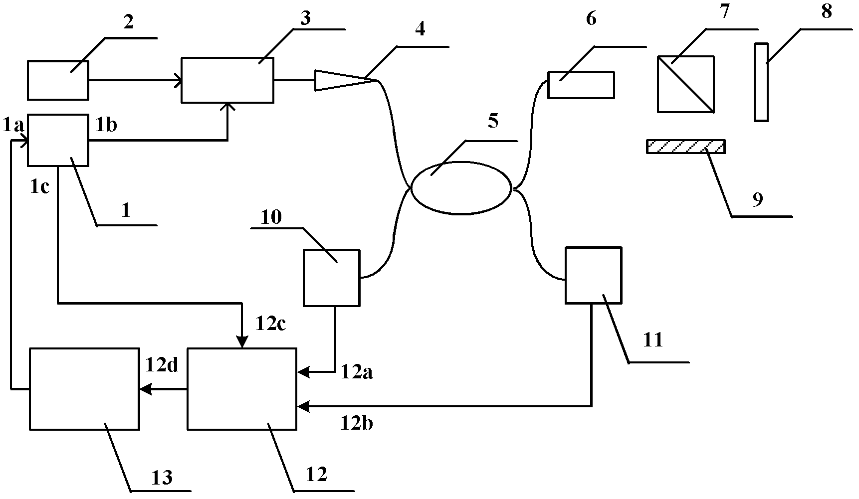
[0026] see first figure 1 , figure 1 It is a structural schematic diagram of the compound current modulation semiconductor laser interferometer of the present invention. As can be seen from the figure, the compound current modulated semiconductor laser interferometer of the present invention includes a light source 3 with a temperature controller 2 driven by a drive power supply 1, an isolator 4, a fiber coupler 5, a collimator 6, a beam splitter 7, With reference to mirror 9, first photodetector 10, second photodetector 11, signal processor 12 and feedback controller 13,

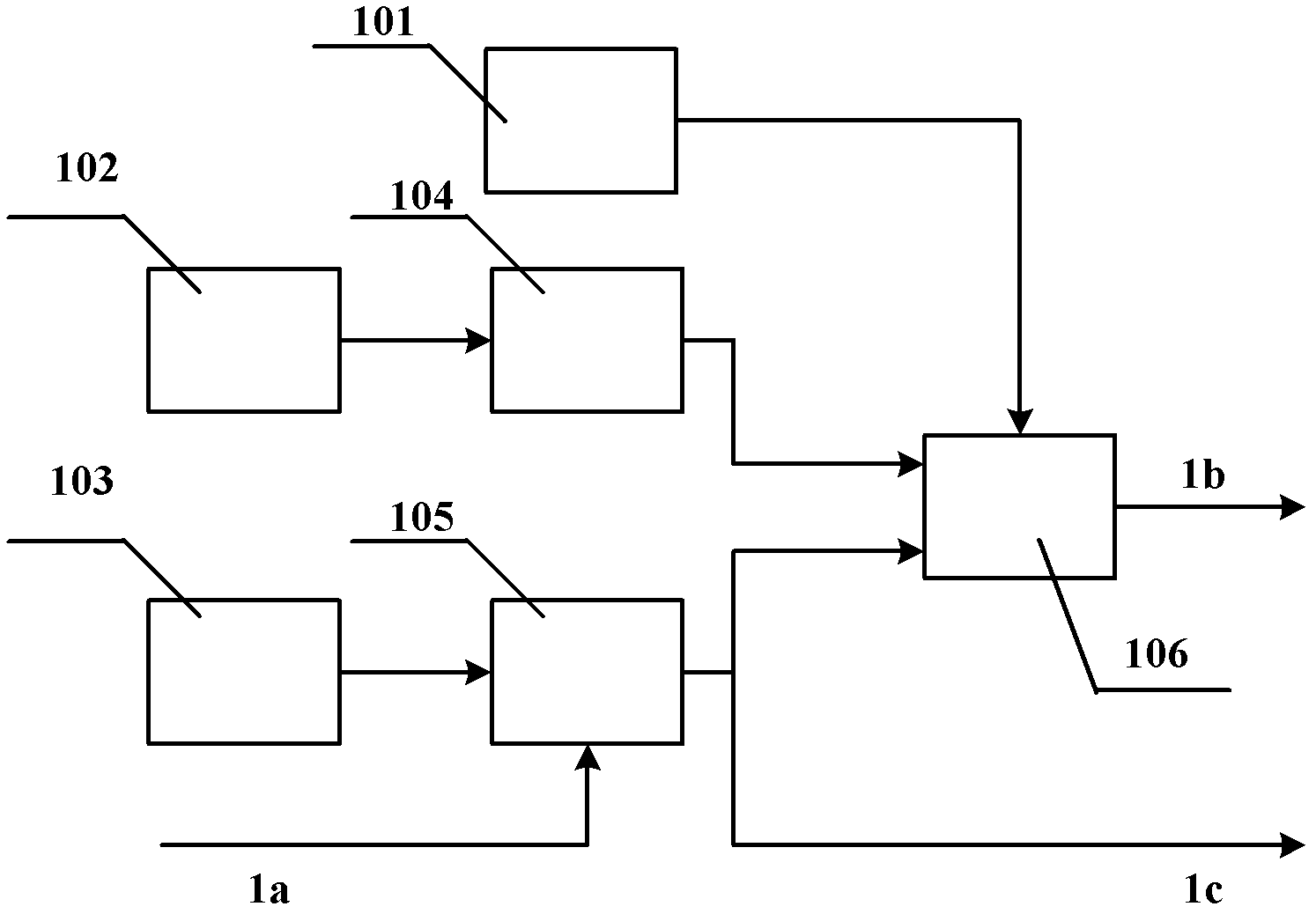
[0027] The input port 1a of the drive power supply 1 is connected to the output port of the feedback controller 13, the first output port 1b is connected to the light source 3, and the second output port 1c i...


PUM


Abstract

The invention provides a laser interferometer for a recombination current modulation semiconductor, which is suitable for measuring the distance. The structure of the laser interferometer comprises a light source, an isolator, an optical fiber coupler, a collimator, a photoelectric detector, a beam splitter, a reference mirror, a signal processor and a feedback controller, wherein the light source is provided with a driving power source and a temperature controller; and a driving power supply provides two sinusoidal modulating current with different frequencies to control the light source. The photoelectric detector converts a received interference signal into an electric signal to be input into the signal processor, so that the distance to be measured can be computed. The feedback controller is connected with the photoelectric detector, and the high-frequency modulating depth is locked by the feedback control. Compared with the prior art, the interferometer provided by the invention is simple and compact in structure, so that the double-sinusoidal phase modulation can be realized due to the recombination current; and the work parameter is locked by means of the feedback control, so that the stability of the system can be enhanced, the measurement precision can be improved, and the real-time measurement can be realized.

Description

technical field [0001] The invention relates to a semiconductor laser interferometer, in particular to a compound current modulation semiconductor laser interferometer. Background technique [0002] Distance measurement is an important technology in the field of test metrology. In recent years, with the development of scientific research and industrial production, higher and higher requirements have been put forward for it. Interferometry technology has been widely studied because of its advantages of high resolution, high precision, non-contact and non-damage. The sinusoidal phase modulation interferometry technology is an international cutting-edge interferometry technology. The semiconductor laser sinusoidal phase modulation interferometer has the advantages of small size, compact structure, simple phase modulation, and high measurement accuracy. In recent years, researchers have paid attention to it. In the field of distance measurement has been greatly developed. [...

Claims


Application Information

Patent Timeline
Patent Type & Authority Applications(China)
IPC IPC(8): G01B9/02G01B11/02
Inventor 王渤帆李中梁王向朝崔丽君
Owner 杭州光学精密机械研究所
Learn More