Device and method for continuously preparing bulk amorphous alloy ingots

A technology for amorphous alloys and preparation equipment, which is applied in the field of continuous preparation at low cost, can solve the problems of reducing the vacuum degree of the vacuum system, high cooling speed, and low cooling speed, so as to prevent the mold from heating up, ensure coaxial alignment, and large The effect of cooling rate

Inactive Publication Date: 2012-08-22
王东
View PDF12 Cites 25 Cited by
  • Summary
  • Abstract
  • Description
  • Claims
  • Application Information

AI Technical Summary

Problems solved by technology

Mainly manifested in the following aspects: 1. Large amorphous alloys contain chemically active elements, and the formation of amorphous state requires high purity of metal melt. The melting and forming of alloys generally need to be carried out in vacuum or inert atmosphere. 2. The forming of large amorphous alloys requires a large cooling rate, while in the continuous casting process of crystalline alloys, the main function of the first cold zone (initial solidification part) is to form the initial solidification slab shell, shape the metal, and cool the slab. It mainly depends on the water spray cooling in the secondary cooling zone, and the distance between the primary cooling and the secondary cooling is long, and the cooling rate is low. When the amorphous alloy is cooled by the same method, the initial cast slab will be crystallized; 3. The solidification shrinkage caused by phase transition basically does not occur in the solidification process of amorphous alloys, which increases the frictional resistance between the billet and the mold; 4. Water vapor not only seriously reduces the vacuum degree of the vacuum system, but also chemically reacts with the alloy, Reduces the glass-forming ability of the alloy

Method used


Image

  • Device and method for continuously preparing bulk amorphous alloy ingots
  • Device and method for continuously preparing bulk amorphous alloy ingots
  • Device and method for continuously preparing bulk amorphous alloy ingots

Examples


Embodiment 1

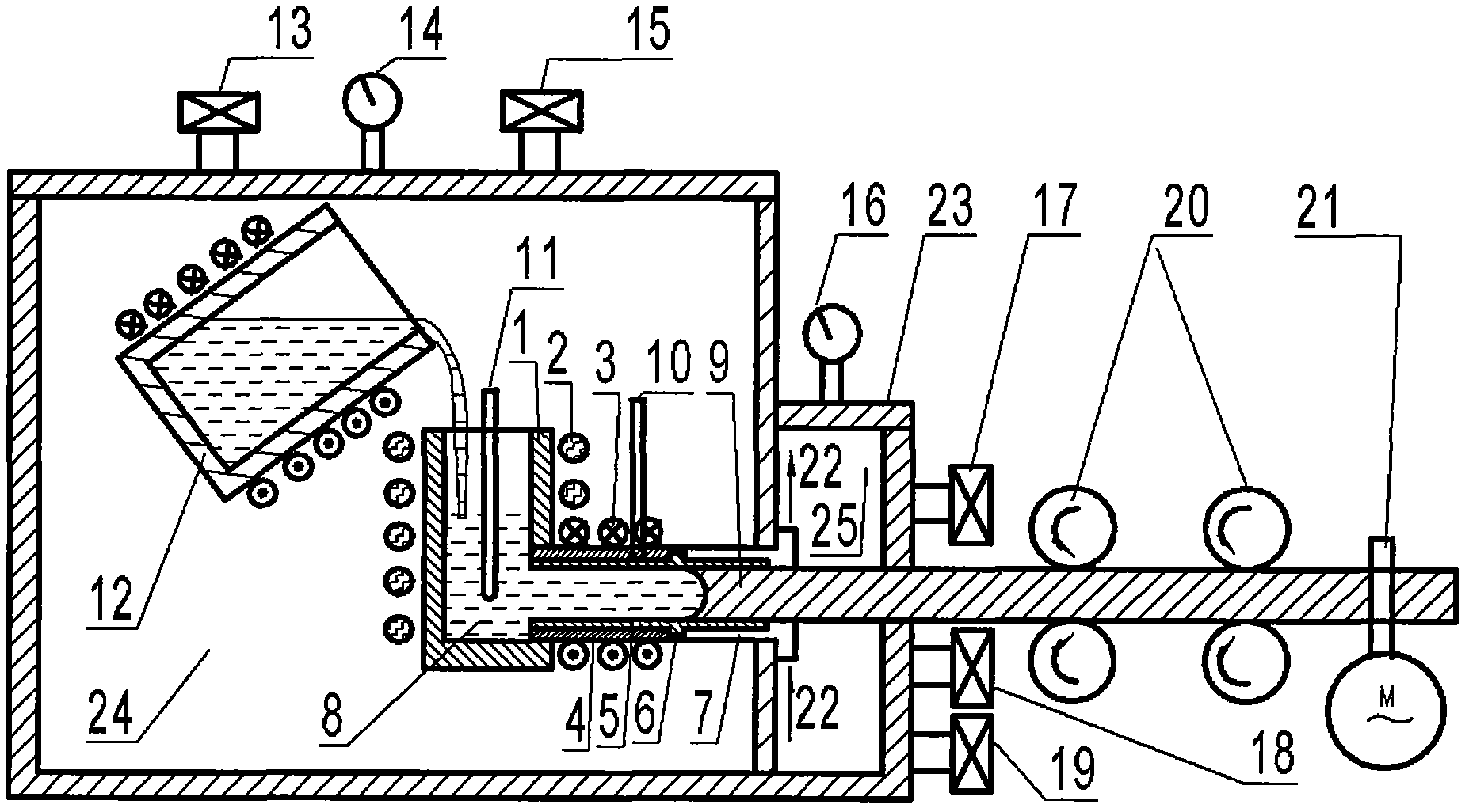
[0033] Example 1: figure 1 It is a horizontal continuous preparation device for large amorphous alloy ingots. It includes a main vacuum chamber 24 and an auxiliary vacuum chamber 25; the boron nitride heat preservation crucible 1 is placed in the main vacuum chamber, the crucible heat preservation device 2 heats the boron nitride heat preservation crucible 1, and the second thermocouple 11 is used to measure the boron nitride heat preservation The temperature of the metal melt 8 in the crucible 1; the sleeve pipe 4 in the nested mold, the thin-walled graphite embedded pipe 5, the heat insulation pad 6 and the front end of the water-cooled copper mold 7 are also located in the main vacuum chamber, and the sleeve pipe 4 and the water-cooled The copper molds 7 are coaxially arranged adjacent to each other, and the casing 4 is connected to the boron nitride heat preservation crucible 1, and is heated by the nested mold heating device 3, and the first thermocouple 10 is used to mea...

Embodiment 2

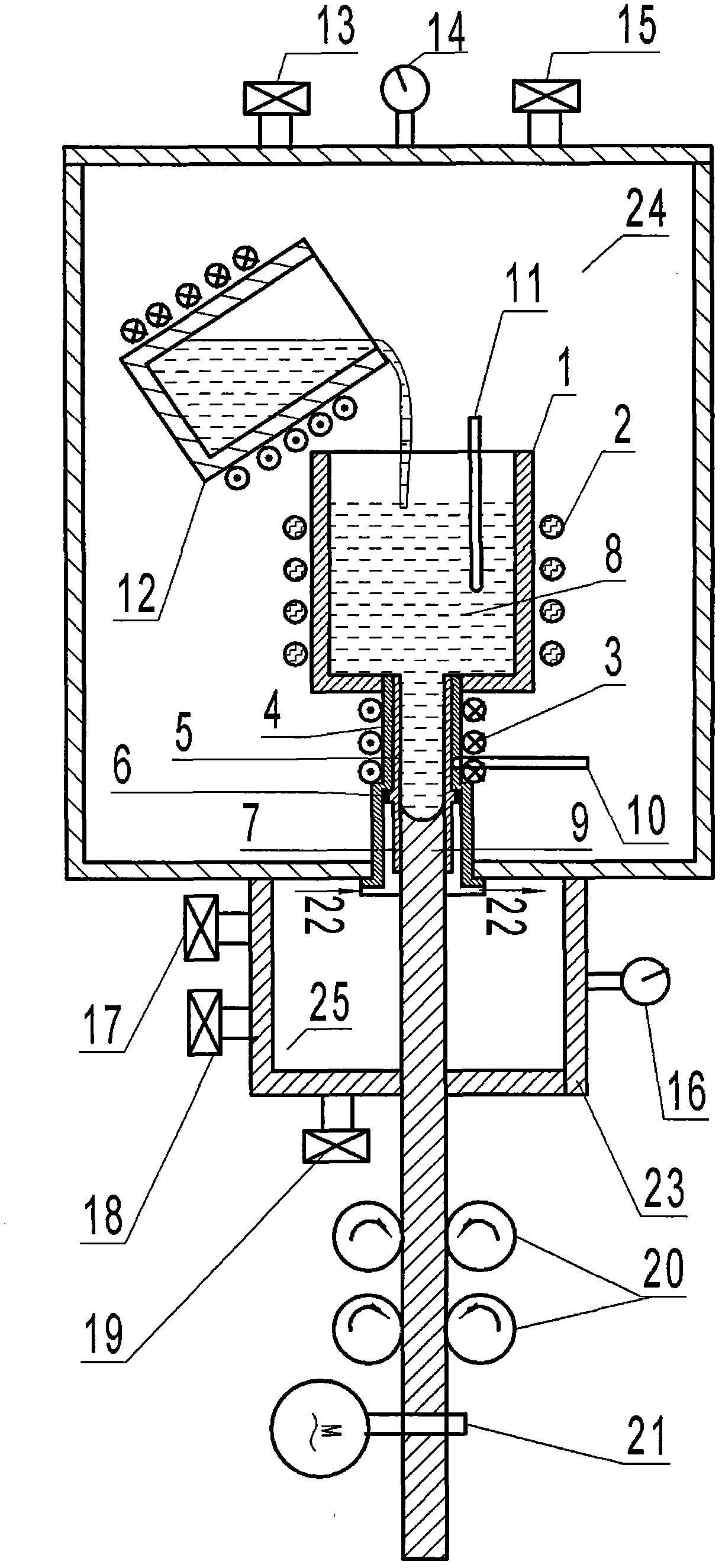
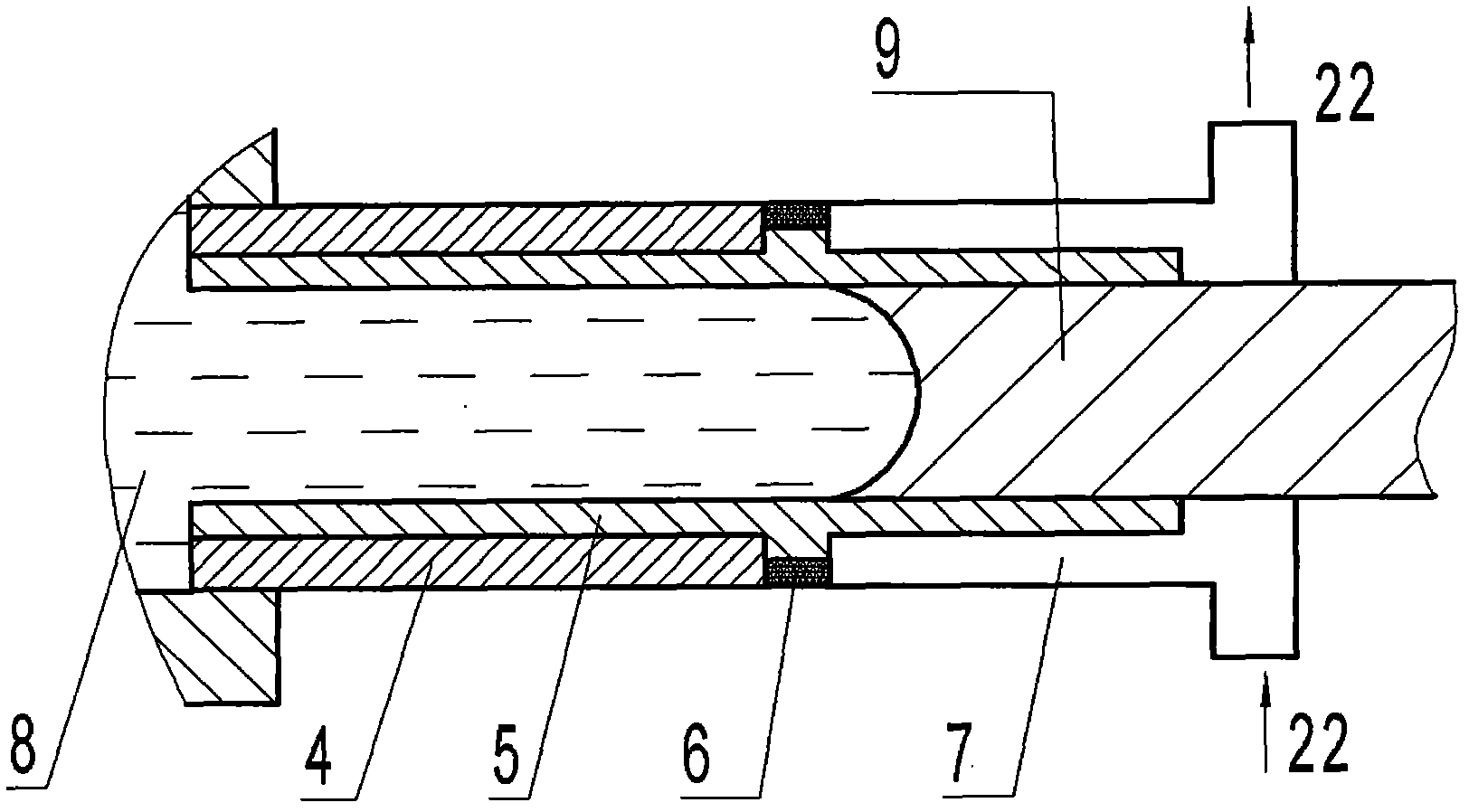
[0043] Example 2: figure 2 It is a vertical continuous preparation device for large amorphous alloy ingots; Figure 4 is a structural schematic diagram of the nested mold of the vertical continuous preparation device; Image 6 It is a structural schematic diagram of the dummy device of the vertical continuous production device. It can be seen from the drawings that the principle and structure of the vertical continuous preparation device and the horizontal continuous preparation device are the same, the difference is that the direction of ingot lead-out is different, so that the nested mold is located under the vacuum chamber, and its axis direction is vertical direction, one end of the sleeve is connected to the bottom of the heat preservation crucible, the other end is fixed to the wall of the main vacuum chamber, and one end of the water-cooled copper mold is embedded in the sleeve.

[0044] The method for continuous preparation of bulk amorphous alloy ingots using a ver...


PUM

PropertyMeasurementUnit
lengthaaaaaaaaaa
thicknessaaaaaaaaaa
lengthaaaaaaaaaa

Abstract

The invention relates to a device and a method for continuously preparing bulk amorphous alloy ingots, which are characterized in that the preparation device comprises two vacuum chambers which are mutually independent. A main vacuum chamber is used for alloy melting and forming, and an auxiliary chamber is used for balancing pressure to facilitate throwing and secondary cooling. The primary cooling section of the preparation device and the method adopts a graphite pipe to be cast with a water cooling copper model embedding nest and is a main cooling part. The secondary cooling section adopts water cooling or natural cooling modes protected by inert gas and is an auxiliary cooling part. The device and the method have the advantages of having large cooling speed, meeting requirements of the bulk amorphous alloy ingots for formation, being simple in structure and capable of conveniently achieving metal continuous formation control and operation under vacuum inert gas atmosphere, and being strong in adaptability and capable of achieving continuous formation of ingots with various section shapes due to the fact that nesting cast with different inner cavity shapes and sizes, thereby being mainly suitable for continuous manufacture fields of the bulk amorphous alloy ingots.

Description

technical field [0001] The invention belongs to the technical field of metal material preparation, in particular to a low-cost continuous preparation technology of bulk amorphous alloys and non-equilibrium solidified materials. Background technique [0002] Amorphous alloys are also called metallic glass. Large amorphous alloys have higher thermal stability than ordinary amorphous alloys. The alloy melt does not crystallize and solidify even at a slow cooling rate of 0.1 to several hundred K / s. As a result, the amorphous liquid phase structure is frozen to a solid state, and its three-dimensional size can reach above the millimeter level. Compared with crystalline metal materials, bulk amorphous alloys have more excellent mechanical, physical, chemical properties and precision molding characteristics. All show good application prospects. [0003] At present, many new research results have been obtained in the field of composition design of bulk amorphous alloys. Nearly 20 ...

Claims


Application Information

Patent Timeline
Patent Type & Authority Applications(China)
IPC IPC(8): B22D11/04B22D11/08B22D11/14B22D27/04C22C45/00
Inventor 王东张涛
Owner 王东
Why Eureka
Try Eureka