Cleaning machine with supporting and thrusting mechanism

A technology of a moving mechanism and a washing machine, which is applied in the direction of using liquid cleaning methods, cleaning methods and utensils, chemical instruments and methods, etc., and can solve problems such as high center of gravity of transportation and transfer, pollution, long transportation path, etc.

Inactive Publication Date: 2012-09-19
SHANGHAI SNA ELECTRONICS TECH DONGTAI
View PDF7 Cites 24 Cited by
  • Summary
  • Abstract
  • Description
  • Claims
  • Application Information

AI Technical Summary

Problems solved by technology

The conveying devices of all the material baskets in this structure are located above the cleaning tank, which still has the disadvantages of high center of gravity, unstable structure, and weak bearing capacity. In this structure, the weight of all materials and the weight of the conveying device need a It is supported by a strong bracket; and the conveying transmission device located above each cleaning tank must adopt a steel structure due to the heavy load
And this structural form also needs to complete several actions of material basket grabbing, lifting, horizontal transfer, lowering, and basket placement every time the material basket is conveyed. The proportion of effective cleaning time in the production cycle is not high, and the work efficiency is not high. high problem
At the same time, in the process of exercise, fine particles caused by motion friction and volatile substances caused by lubricant will inevitably be produced, which will just fall into the cleaning tank below it, so it is d

Method used


Image

  • Cleaning machine with supporting and thrusting mechanism
  • Cleaning machine with supporting and thrusting mechanism
  • Cleaning machine with supporting and thrusting mechanism

Examples


Embodiment Construction

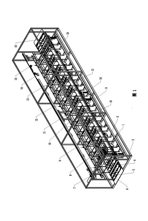
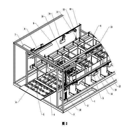
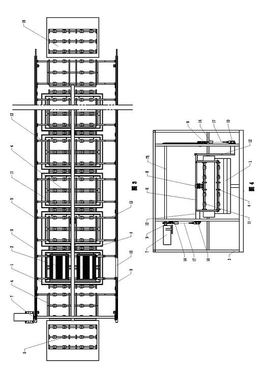
[0026] exist figure 1 , figure 2 In the cleaning machine with lifting and pushing mechanism shown, the main body of the frame 3 is a hexahedral rectangular frame structure, and the outside of the frame 3 is covered with panels or door and window assemblies, and there is also a cleaning tank between the internal cleaning tank area and other components. The partition makes the cleaning tank area of ​​the washing machine form a relatively closed working space. Ten cleaning tanks 1 are arranged in sequence along the length direction in the frame-type frame 3, and the distance between adjacent cleaning tanks 1 is equal to each other. on the frame of the lower part. The pipeline system used to provide the cleaning liquid leads to the cleaning tank 1. An ultrasonic system can also be installed in the cleaning tank 1 according to the process requirements. According to the different cleaning requirements of silicon materials and wafers, each cleaning tank 1 is filled with different ...


PUM


Abstract

The invention discloses a cleaning machine with a supporting and thrusting mechanism, which comprises a rack and a plurality of cleaning tanks, wherein a lifting bracket used for supporting material baskets is arranged in each cleaning tank; at least one side edge of each lifting bracket is connected with a lifting cross beam through a bracket connecting rod; a lifting driving mechanism mounted on the rack can drive the lifting brackets to be lifted to and fro in the vertical direction through the lifting cross beam; horizontal material basket push rods used for horizontally pushing the material baskets to move are further arranged above the cleaning tanks and are driven by a horizontal driving mechanism; fixed brackets are fixedly arranged between adjacent cleaning tanks; upper bearing surfaces of the fixed brackets are positioned in the same bearing plane as bearing surfaces of the lifting brackets lifted to high positions; and the bearing plane is higher than tank openings of the cleaning tanks. The cleaning machine has the advantages of stability and reasonableness in structure and great carrying capacity; and particularly, a cleaning and conveying path of the cleaning machine is reasonable, the effective cleaning time is long and the work efficiency is high.

Description

technical field [0001] The invention relates to manufacturing equipment in the semiconductor and solar energy industries, in particular to a tank-type cleaning machine for materials such as silicon materials and silicon wafers. Background technique [0002] Cleaning of silicon materials and silicon wafers is an important link in the manufacturing process of silicon materials in the solar energy industry and the semiconductor industry. Its purpose is to remove metal ion pollution, organic pollution or particle pollution on the surface of silicon materials or silicon wafers, thereby ensuring its purity and product quality. [0003] The silicon material and silicon wafer cleaning machine is mainly composed of a cleaning tank installed on the frame, a cleaning liquid pipeline system, an ultrasonic system, a heating system, a cleaning throwing device, a material basket conveying system and an electric control part. The material basket is used to carry the silicon wafers and sili...

Claims


Application Information

Patent Timeline
IPC IPC(8): B08B3/04B08B13/00
Inventor 滕明倪加乐
Owner SHANGHAI SNA ELECTRONICS TECH DONGTAI
Why Eureka
Try Eureka