Supercritical water oxidation fluid injection production system using nitrogen as protective film and process using same

A supercritical water oxidation and protective film technology, applied in the field of energy and environment, can solve the problems of reactor wall corrosion, harsh reaction conditions, reactor or system pipeline blockage, etc., to reduce the viscosity of heavy oil, increase oil recovery, The effect of broad application prospects

Inactive Publication Date: 2012-09-19
SHANDONG UNIV
View PDF3 Cites 10 Cited by
  • Summary
  • Abstract
  • Description
  • Claims
  • Application Information

AI Technical Summary

Problems solved by technology

[0007] However, the supercritical water oxidation reaction conditions are harsh. Under the conditions of high temperature, high pressure and oxygen, the reactor wall will be corroded; in addition, supercritical water is a non-polar solvent, and the solubility of inorganic salts in supercritical water will drop sharply. , thus forming the precipitation of inorganic salts, causing blockage of the reactor or system piping in severe cases
Therefore, the problems of corrosion and clogging have become bottlenecks restricting the development

Method used


Image

  • Supercritical water oxidation fluid injection production system using nitrogen as protective film and process using same
  • Supercritical water oxidation fluid injection production system using nitrogen as protective film and process using same

Examples


Example Embodiment

[0034] Example 1:

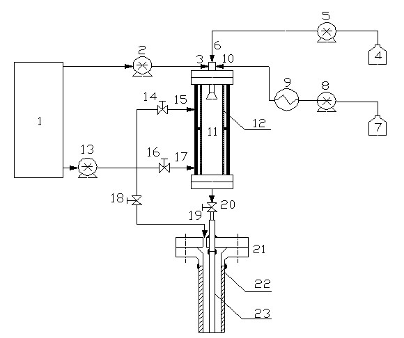
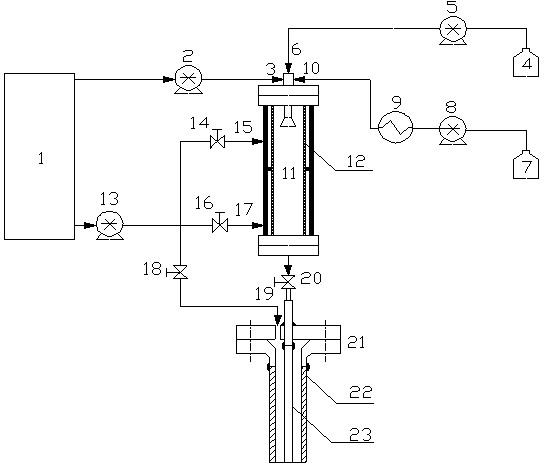
[0035] Such as figure 1 As shown, the crude oil in the fuel tank 4 is boosted to 23 MPa by the fuel booster pump 5 and injected into the gas film reactor 11 from the fuel inlet 6; the oxygen generated by the air separation plant 1 is boosted to 23 MPa by the oxygen booster pump 2, The gas film reactor 11 is injected from the oxygen inlet 3; the water in the water storage tank 7 is boosted to 23MPa by the water booster pump 8, preheated to 300-600°C by the water preheater 9, and injected from the upper part through the water inlet 10 Gas film reactor. After the three are mixed through the nozzle, a supercritical water oxidation reaction occurs in the upper part of the film reactor 11 to generate carbon dioxide and water. A part of the nitrogen generated by the air separation plant 1 is pressurized to 23MPa by the nitrogen booster 13 and divided into upper and lower channels. After the flow is adjusted by the first and second nitrogen flow regulating valves 14...

Example Embodiment

[0037] Example 2

[0038] The difference between this embodiment and the first embodiment is that the crude oil is replaced with high-concentration oil production wastewater. While generating multiple thermal fluids, it can also realize the harmless treatment of oil production wastewater, which has a good environmental effect. The rest of the process and implementation Example 1 is the same.


PUM


Abstract

The invention discloses a supercritical water oxidation fluid injection production system using nitrogen as a protective film. The injection-production system comprises an air separation plant, an air film reactor, a shaft and an injection pipeline disposed in the shaft. An oxygen outlet of the air separation plant is communicated with an oxygen inlet at the upper end of the air film reactor through an oxygen booster pump. A nitrogen outlet of the air separation plant is communicated with an upper nitrogen inlet, a lower nitrogen inlet and a gap between the shaft and the injection pipeline through a nitrogen booster pump. The upper nitrogen inlet and the lower nitrogen inlet are reserved on one side of the air film reactor. A fuel inlet and a water inlet which are communicated with a fuel device and a water booster heating device respectively are reserved at the upper end of the air film reactor. An outlet which is communicated with the injection pipeline is reserved at the lower end of the air film reactor. The invention further discloses an injection-production process using the system. Oxygen is used as oxidant and the nitrogen is used as a protective film of the reactor and the shaft, fuel is oxidized through supercritical water, generated multiple thermal fluids are injected into an oil well, and accordingly, viscosity of thickened oil is lowered and oil recovery rate is enhanced.

Description

[0001] technical field [0002] The invention relates to the fields of energy and environment, in particular to a supercritical water oxidation fluid injection and production system using nitrogen as a protective film and a process thereof. Background technique [0003] Reducing costs and maximizing the extraction of heavy oil and super heavy oil are common issues facing the oil industry in the world today. Due to the high viscosity of heavy oil, it brings great difficulties to mining, gathering and processing. Thermal oil recovery by steam injection is an effective means to develop heavy oil reservoirs. The law of steam injection huff and puff is that the oil production reaches its peak in the fourth and fifth cycle, and then with the increase of the huff and puff cycle, the oil production in each cycle gradually decreases, the comprehensive water cut increases, and the production effect becomes worse day by day. The main reason for the poor production effect after multip...

Claims


Application Information

Patent Timeline
IPC IPC(8): E21B43/24
Inventor 马春元陈桂芳陈守燕张凤鸣徐纯燕张勇
Owner SHANDONG UNIV
Why Eureka
Try Eureka