Fuel delivery pump with floated cycloid rotor

An oil pump and suspension technology, applied in the field of auto parts, can solve problems such as large volume ratio, and achieve the effects of large volume ratio, saving money and increasing service life

Active Publication Date: 2012-09-19
SHANDONG XINYA IND +1
View PDF10 Cites 13 Cited by
  • Summary
  • Abstract
  • Description
  • Claims
  • Application Information

AI Technical Summary

Problems solved by technology

[0004] The purpose of the present invention is to solve the problem of a cycloidal rotor oil delivery pump with simple structure, low noise, large volume ratio and long service life as described in the background technology, and provide a suspension type cycloidal rotor oil delivery pump, a suspension type cycloidal rotor oil delivery pump The oil delivery pump is composed of an oil delivery pump body 1, an outer rotor 2, an inner rotor 3 and a ten-byte 4. The outer rotor 2 is placed in the pump body cavity 101 of the oil delivery pump body 1, and the inner rotor 3 is in the outer rotor 2 and connected with the oil delivery pump body 1. The inner rotor shaft 102 is rotationally connected, and the ten-piece 4 is placed in the ten-piece installation groove 303 of the inner rotor 3. It is characterized in that the oil delivery pump body 1 has an integral structure, and in the circular pump body cavity 101, the inner rotor The shaft 102 is eccentric with the pump body cavity 101 and is vertically placed on the bottom surface of the pump body cavity 101, and the center of circle of the pump body cavity 101 bottom surface is O 1 , the center of the inner rotor shaft 102 on the bottom surface of the pump body cavity 101 is O 2 , through O 2 The radius of the bottom surface of the pump body cavity 101 is O 1 The length of A is r, O 2 deviated from O 1 The distance is d, and the radius O...

Method used


Image

  • Fuel delivery pump with floated cycloid rotor
  • Fuel delivery pump with floated cycloid rotor
  • Fuel delivery pump with floated cycloid rotor

Examples


Embodiment Construction

[0025] The present invention will be further described below in conjunction with the embodiments and the accompanying drawings.

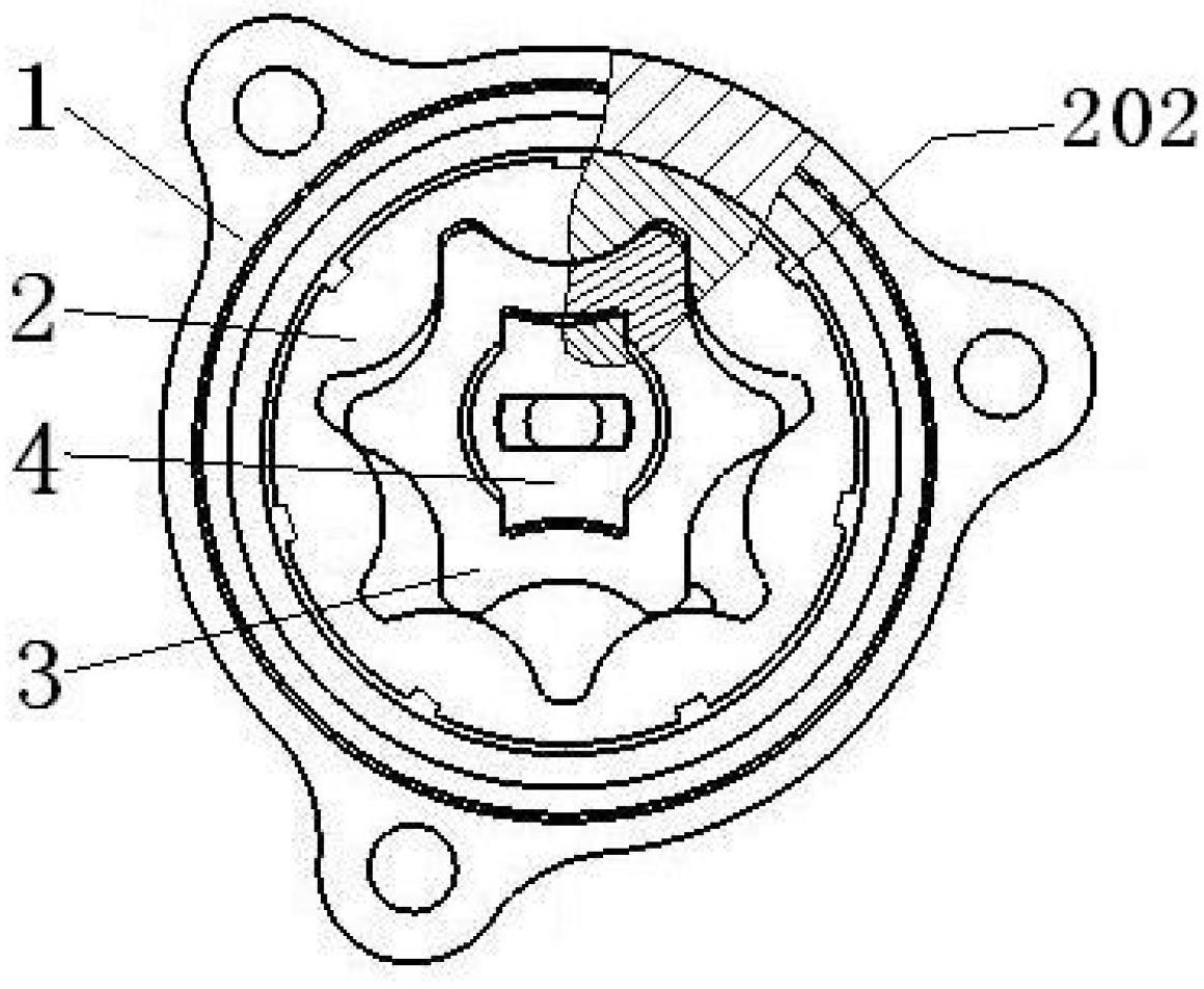
[0026] figure 1 It is a structural schematic diagram of an embodiment of the cycloid fuel delivery pump in the high-pressure common rail fuel injection system. The cycloid fuel delivery pump in the high-pressure common rail fuel injection system is composed of a fuel delivery pump body 1, an outer rotor 2, an inner rotor 3 and a ten-byte 4. The outer rotor 2 is placed in the pump body cavity 101 of the oil delivery pump body 1, the inner rotor 3 is rotationally connected with the inner rotor shaft 102 of the oil delivery pump body 1 in the outer rotor 2, and the ten section 4 is placed in the ten section installation of the inner rotor 3 In the slot 303.

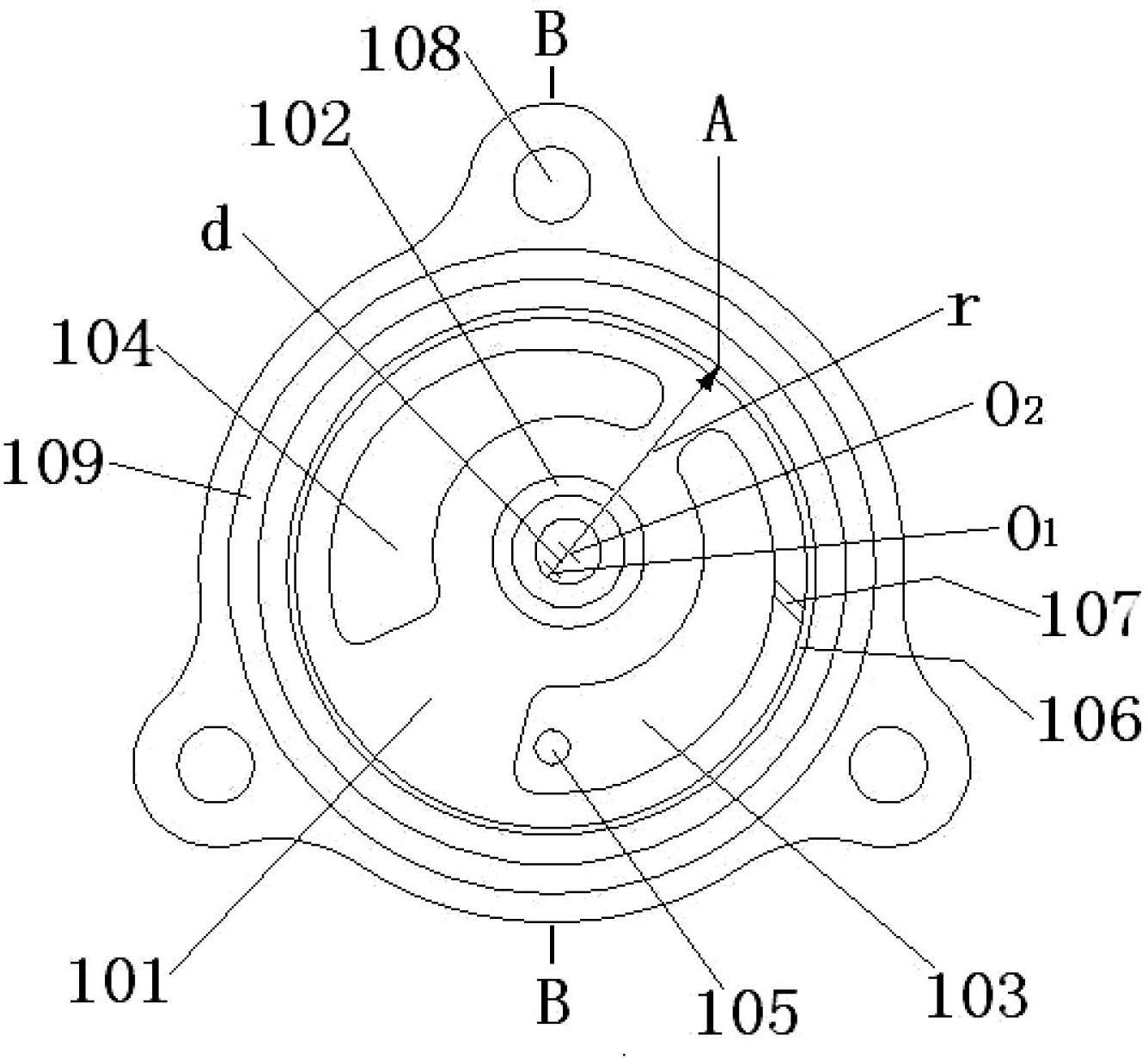
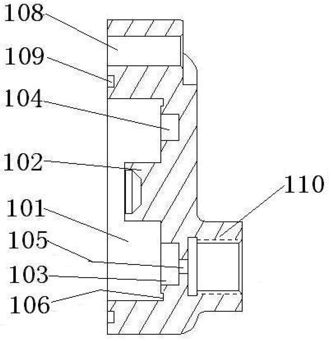
[0027] Such as figure 2 and image 3 In the structural diagram of the oil delivery pump body shown, the oil delivery pump body 1 is an integrated structure processed by powder metallurgy techn...


PUM

PropertyMeasurementUnit
Widthaaaaaaaaaa
Depthaaaaaaaaaa
Widthaaaaaaaaaa

Abstract

The invention belongs to the technical field of auto parts, and relates to a fuel delivery pump with a floated cycloid rotor. The fuel delivery pump with the suspended cycloid rotor comprises a fuel delivery pump body, an outer rotor, an inner rotor and a universal joint. The fuel delivery pump body is in an integral structure. A transverse guide groove is reserved on the bottom surface of a pump inner cavity between the upper portion of a right wall of a low pressure oil cavity and the inner wall of the pump inner cavity. Seven axial through grooves on the outer wall of the outer rotor are distributed at central radial positions of inner wall tooth sections of the outer rotor. When the inner rotor and the outer rotor rotate, fuel flows along the transverse guide groove and the axial through grooves to positions to be lubricated. An oil film is formed between the outer wall of the outer rotor and the inner wall of the pump inner cavity, the outer rotor cannot be contacted with the fuel delivery pump directly under the action of liquid surface tension, the outer rotor is floated in the fuel delivery pump body, and accordingly friction between the outer rotor and the fuel delivery pump body is avoided, and the service life of the fuel delivery pump is prolonged. The fuel delivery pump with the suspended cycloid rotor is stable in operation, low in pulsating, low in noise and high in volume efficiency, and is applicable to automotive diesel engine fuel injection systems.

Description

technical field [0001] The invention belongs to the technical field of auto parts, in particular to a suspension type cycloidal rotor oil delivery pump. Background technique [0002] Automobile diesel engines generally have the problem of insufficient starting fuel supply at low temperature and low speed, which cannot meet the needs of high-pressure fuel systems. The fuel delivery pumps of the mechanical fuel injection system currently used, including vane pumps, gear pumps and plunger pumps, all have pressure and Large flow pulse, high noise, low volumetric efficiency, poor low-speed oil absorption and other defects lead to the emission of domestic automobile diesel engines not meeting the international requirements of Euro Ⅲ or even Euro Ⅳ and Euro Ⅴ standards. [0003] In the high-pressure common rail system of a diesel engine, in order to ensure that the fuel circulates in the low-pressure oil circuit system, and to deliver sufficient flow and a certain pressure of fuel ...

Claims


Application Information

Patent Timeline
IPC IPC(8): F04C2/10F04C15/00F02M37/06
Inventor 张卫军周明乌江牟学利胡阳谢之峰张秉鉴兰旭东黄金鹏黄旭东李炳河陈伟刘健岳志远
Owner SHANDONG XINYA IND
Why Eureka
Try Eureka