Solid waste incinerator body

A solid waste and incinerator technology, applied in incinerators, non-flammable liquid/gas transportation, combustion methods, etc., can solve problems such as furnace temperature drop, resource waste, and furnace temperature instability, so as to reduce heat loss, Improved thermal efficiency and remarkable energy saving effect

Inactive Publication Date: 2012-10-03
袁永扬
View PDF5 Cites 5 Cited by
  • Summary
  • Abstract
  • Description
  • Claims
  • Application Information

AI Technical Summary

Problems solved by technology

These incinerators have the following disadvantages: (1) The combustion temperature in the combustion zone in the furnace is in the range of 800-900°C, the combustion temperature is low, the combustion effect is poor, and a large amount of harmful gases such as dioxins will be produced; (2) , During the combustion process, a large amount of flue gas (such as nitrogen oxides, carbon dioxide, sulfur dioxide, and harmful gas dioxins produced by incomplete combustion, etc.) will be emitted to cause secondary pollution; (3), auxiliary fuels (such as (coal, diesel, etc.) will increase the combustion cost, consume a lot of energy, and cause waste of resources; (4), because the combustion aid used in the combustion process of garbage is air, and the nitrogen in the air does not participate in the combustion reaction, and it is To absorb a large amount of heat, resulting in large heat loss and low thermal efficiency
In short, these furnaces have complicated furnace body structure, large furnace volume, large air volume, large flue gas discharge, large dust, and large heat loss, which are neither energy-saving nor environmentally friendly.
[0004] In the existing solid waste incinerator, due to the continuous discharge of a large amount of flue gas, part of the heat of solid waste incineration will be taken away with the flue gas emission, so that the furnace temperature will drop; Low, so it is difficult to burn, and the garbage needs to be dried in advance, which requires a lot of hot air, and part of the heat in the furnace is consumed, which makes the furnace temperature drop; at the same time, due to the large furnace volume of the incinerator, the heat dissipation area of ​​the inner surface of the furnace is large. , The heat dissipation speed is fast and the heat dissipation is large, and part of the heat energy in the furnace is consumed, which makes the furnace temperature drop, resulting in low thermal efficiency of the entire incinerator
[0005] In the existing solid waste incinerators, the combustion accelerants that participate in the combustion and oxidation reactions all use oxygen in the air. Due to the complex composition of solid waste, the difference in calorific value is large, resulting in unstable furnace temperature. When the calorific value of incineration When the temperature is low, fuels with high calorific value such as diesel or coal are generally added to maintain a stable furnace temperature, which consumes part of the energy. When the plastic in solid waste is not fully burned under the condition of an oxidant, a large amount of dioxin, etc. will be produced. Toxic and harmful gases, causing serious environmental pollution
The complete incineration of solid waste usually needs to increase the amount of air entering the furnace to increase the end flow, so that the air and solid waste can form a boiling state in the furnace, but this will lead to an increase in the amount of fly ash in the flue gas , which increases the difficulty of flue gas purification treatment and increases the treatment cost

Method used


Image

  • Solid waste incinerator body
  • Solid waste incinerator body
  • Solid waste incinerator body

Examples


Embodiment Construction

[0021] The present invention is described in further detail by the following examples.

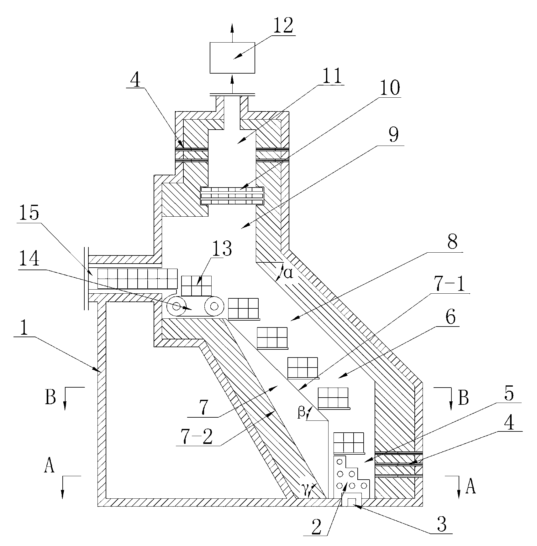
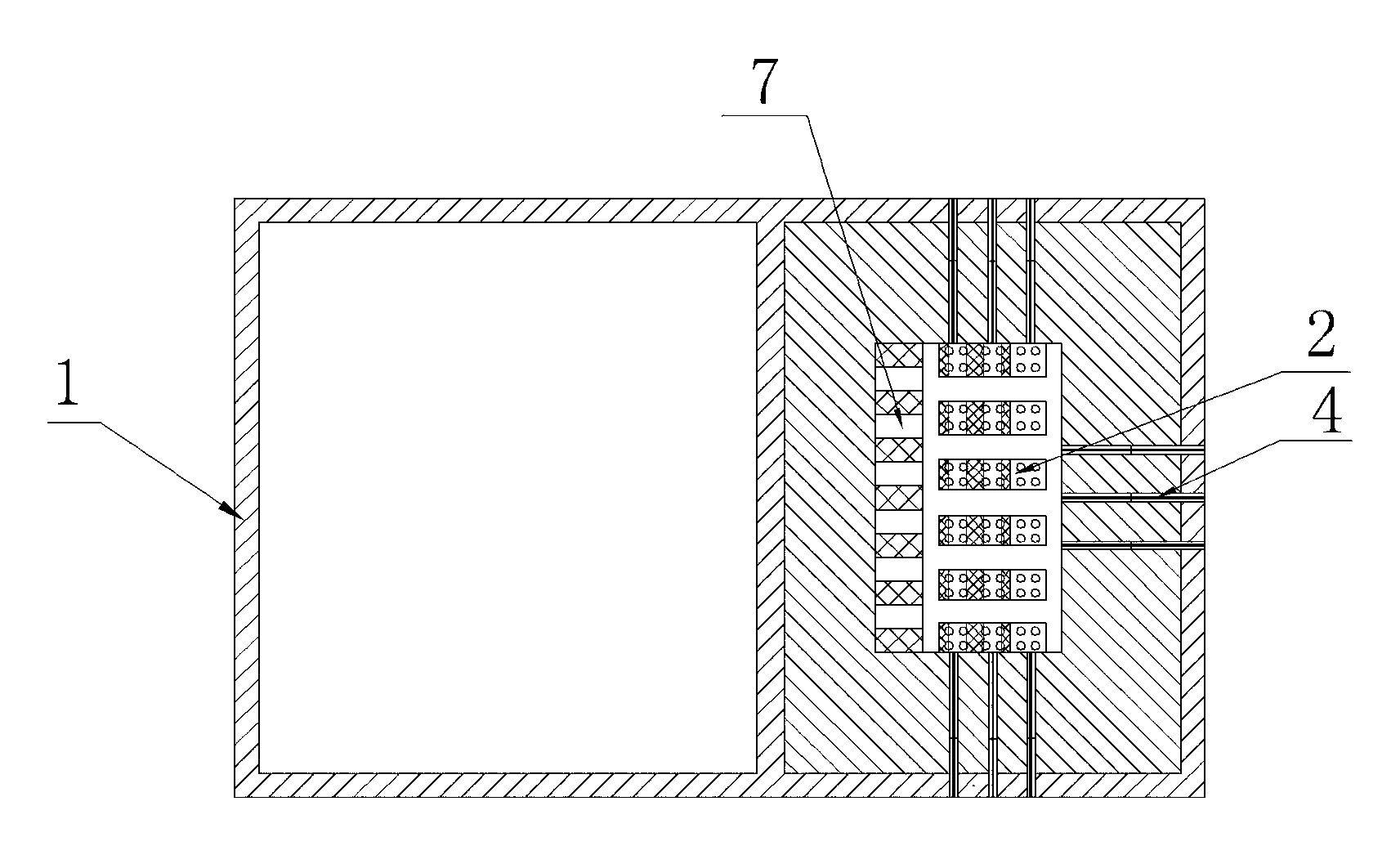
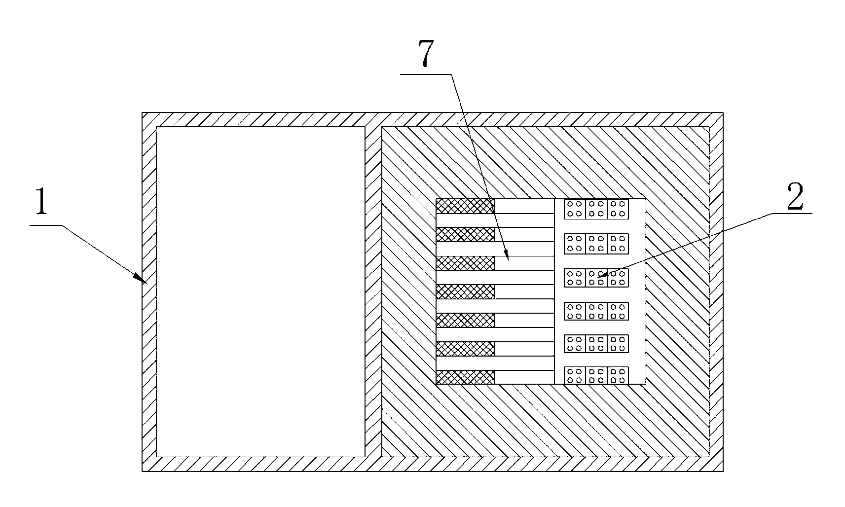
[0022] see figure 1 — image 3As shown, a solid waste incinerator body consists of a vertically structured incinerator body 1 , a vertically structured incinerator hearth 9 , a high temperature resistant belt conveyor 14 , a boiler hearth 11 , and an induced draft fan 12 . The furnace 9 of the incinerator is provided with a drying area 8 , a pyrolysis area 6 and a combustion area 5 sequentially from top to bottom. The bottom of the combustion area 5 is provided with an ash outlet 3 , and the ash outlet 3 is provided with a grid 2 . The cross-section of the incinerator hearth 9 is square, and a group of heated kangs 7 parallel to each other and vertically arranged are arranged inside the drying zone 8, the pyrolysis zone 6, and the combustion zone 5 of the incinerator hearth 9, and the heated kang surface 7-1 The included angle β=40°-50° angle with the horizontal plane, and the included a...


PUM


Abstract

The invention provides a solid waste incinerator body. The incinerator body and a hearth of an incinerator are of vertical structures. The hearth is sequentially provided with a drying zone, a pyrolyzing zone and a burning zone from top to bottom, a group of fiery pits are arranged on the inner side of the hearth, a group of spray guns are respectively arranged on the outer side, the left side and the right side of the burning zone, a blocky compressed solid waste inlet is arranged on the outer side of the upper portion of the hearth, a boiler furnace and a draught fan are arranged at the top of the hearth, a group of spray guns are arranged on the side wall of the boiler furnace, the draught fan enables smoke to be discharged out of the incinerator, oxygen enriched gas formed by mixing residual smoke and pure oxygen is led to the third group of spray guns of the burning zone and the group of spray guns of the boiler furnace. The incinerator hearth is small in volume and large in solid waste disposal capacity, and the solid waste incinerator body is rapid in burning speed, good in effect, capable of disposing solid waste of various kinds at the same time, energy-saving, environment-friendly and remarkable in effect.

Description

technical field [0001] The invention relates to the technical field of solid waste incinerators, in particular to a furnace body of a solid waste incinerator. Background technique [0002] Solid waste includes: urban road cleaning garbage, domestic garbage, catering garbage, medical waste, agricultural product processing waste, feces, waste plastics, tires, organic sludge and hazardous waste such as tanning sludge, electroplating sludge, printing and dyeing sludge etc. The incinerators of existing waste incineration power plants generally burn waste in the range of 800-900 ° C. It is impossible for the incinerators of waste incineration power plants to incinerate waste such as medical waste or sludge, let alone incinerate hazardous waste thing. Medical waste incinerators generally require a furnace temperature of 1200°C. Existing medical waste incinerators need to add a large amount of fuel to assist combustion, and the operating costs are high, so it is impossible to use ...

Claims


Application Information

Patent Timeline
Patent Type & Authority Applications(China)
IPC IPC(8): F23G5/02F23L7/00F23G5/44
CPCY02E20/322Y02E20/34
Inventor 袁永扬
Owner 袁永扬
Why Eureka
Try Eureka