Method for implementing microwave photonic filter based on photonic crystal

A technology of microwave photonics and photonic crystals, applied in light guides, optics, instruments, etc., can solve the problems of low refractive index of delay unit material groups, unfavorable device miniaturization and integration, and large delay unit scale, so as to reduce the difficulty of production , Light field localization is good, the effect of small volume

Inactive Publication Date: 2012-10-10
BEIJING UNIV OF POSTS & TELECOMM
View PDF7 Cites 12 Cited by
  • Summary
  • Abstract
  • Description
  • Claims
  • Application Information

AI Technical Summary

Problems solved by technology

Each of these filters has its own advantages, such as reconfigurability (Reference 7), low coherent dispersion (Reference 9), or the ability to form a single-bandwidth frequency response (Reference 8), but they ...

Method used


Image

  • Method for implementing microwave photonic filter based on photonic crystal
  • Method for implementing microwave photonic filter based on photonic crystal
  • Method for implementing microwave photonic filter based on photonic crystal

Examples


Embodiment Construction

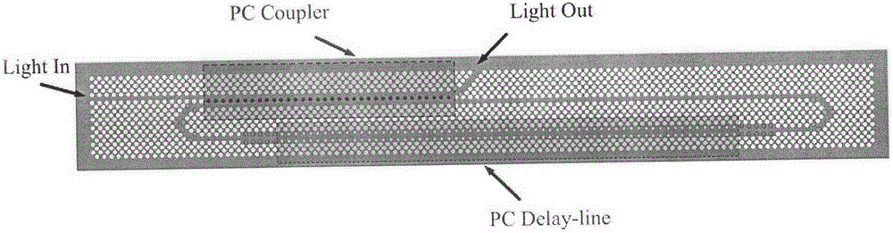
[0035] Microwave photonic filter structures based on photonic crystals such as figure 1 shown. The silicon-based two-dimensional triangular lattice air hole structure used in this structure has a lattice constant a=350nm, an ordinary air hole radius r=0.35a, and a refractive index n of the dielectric silicon si = 3.4. It contains two main parts: coupling beam splitter (PC Coupler) and slow optical waveguide delay line (PC Delay-line), and a 180° U-shaped curved waveguide connecting these two parts. The 1550nm TE mode narrow-band light is input from the Light In port, filtered by the narrow-band filter, and output from the Light Out port. The transmission spectrum shows the spectral characteristics of FSR=60GHz and notch depth of 10dB.

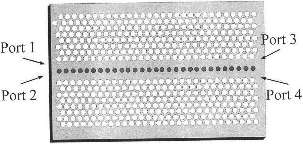
[0036] figure 2 is a schematic diagram of the structural model of a photonic crystal coupling beam splitter, which contains two W1 waveguides with a waveguide width of A row of air holes is spaced between the two waveguides, and the radiu...


PUM

PropertyMeasurementUnit
Lattice constantaaaaaaaaaa

Abstract

The invention relates to a method for implementing a microwave photonic filter based on a photonic crystal. A bent waveguide integrated coupling beam splitter and a slow light waveguide delay line are used on the same photonic crystal, so that a system function of the filter has the bandpass filter characteristic of trapped wave depth of 10dB in a free frequency spectral range of 130 GHz at 1,550 nanometers; and the function of filtering residual edge bands of a light generation millimeter wave signal can be realized. By using a bidimensional photonic crystal structure compared with an optical fiber ring structure, the size of the filter can be greatly reduced; and the method is favorable for minimizing and integrating the device.

Description

technical field [0001] The invention relates to a method for realizing a microwave photon filter based on a photonic crystal, and belongs to the technical field of optical filters. Background technique [0002] At present, most of the communication services in our country are concentrated below 3GHz, and almost all the existing low-frequency frequency resources have been occupied, but the frequency resources above 3GHz are less utilized, especially for the two atmospheric transmissions in the 24GHz and 60GHz frequency bands. High loss window. In order to make full use of the 60GHz license-free frequency band, RoF technology came into being. This technology fully combines the characteristics of optical fiber and high-frequency radio wave transmission, low-cost radio frequency signal wired transmission and ultra-wideband wireless access. [0003] Generally speaking, the RoF system uses a radio frequency oscillator to convert the baseband signal to the radio frequency band, an...

Claims


Application Information

Patent Timeline
IPC IPC(8): G02B6/122
Inventor 纪越峰田慧平申冠生刘伟佳张艳红
Owner BEIJING UNIV OF POSTS & TELECOMM
Why Eureka
Try Eureka