Coil for stainless steel framed Nb3Sn superconducting solenoid

A technology of solenoid coils and superconducting magnets, applied in superconducting magnets/coils, magnetic objects, plastic/resin/wax insulators, etc., to achieve the effects of stable ceramic coating, improved thermal shock resistance, and excellent thermal conductivity

Active Publication Date: 2012-10-10
INST OF ELECTRICAL ENG CHINESE ACAD OF SCI
View PDF6 Cites 21 Cited by
  • Summary
  • Abstract
  • Description
  • Claims
  • Application Information

AI Technical Summary

Problems solved by technology

[0011] The purpose of the invention is to solve the existing Nb 3 There are problems in the coil frame material and insulation performance in the coi

Method used


Image

  • Coil for stainless steel framed Nb3Sn superconducting solenoid
  • Coil for stainless steel framed Nb3Sn superconducting solenoid
  • Coil for stainless steel framed Nb3Sn superconducting solenoid

Examples


Embodiment 1

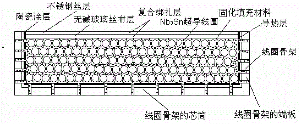
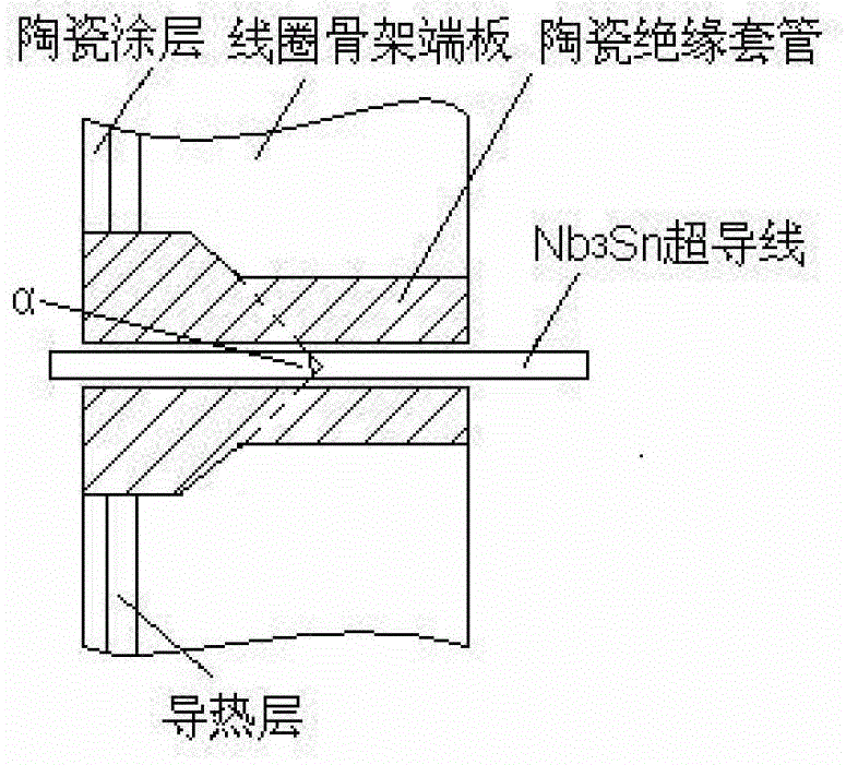
[0034] The wire of the solenoid coil of the superconducting magnet is made of Nb in bronze process 3 Sn superconducting wire, the wire is insulated by an alkali-free glass cloth sleeve. The superconducting wire has a bare diameter of 0.9mm and an insulated diameter of 1.05mm. Nb 3 The inner diameter of the Sn coil is 41mm, the outer diameter is 64mm, and the length is 150mm. There are 12 layers of superconducting wires in the coil, with a total of about 1655 turns. The coil bobbin is made of non-magnetic stainless steel, and the coil bobbin is composed of a straight tubular core barrel and end plates located at both ends of the core barrel. Both the outer surface of the core barrel and the inner side of the end plate have a silver heat conduction layer and an alumina ceramic coating prepared by a plasma spraying process; the heat conduction layer is located between the ceramic coating and the skeleton. Nb wound with ceramic coating 3 In the Sn superconducting coil, the ou...

Embodiment 2

[0037] Preparation of stainless steel skeleton Nb 3 The Sn superconducting magnet solenoid coil, the preparation method and process parameters are the same as those in Example 1, except that the diameter of the spherical ceramic particles in the solidified filling material is 300 microns. the Nb 3 The Sn coil is placed in a 4.2K low temperature environment and the test shows that the Nb 3 Sn coils exhibit good low-temperature critical properties.

Embodiment 3

[0039] Preparation of stainless steel skeleton Nb 3 The Sn superconducting magnet solenoid coil, the preparation method and process parameters are basically the same as those in Example 1, except that the diameter of the spherical ceramic particles in the solidified filling material is 150 microns. the Nb 3 The Sn coil is placed in a 4.2K low temperature environment and the test shows that the Nb 3 Sn coils exhibit good low-temperature critical properties.


PUM

PropertyMeasurementUnit
Diameteraaaaaaaaaa
Inductanceaaaaaaaaaa
Diameteraaaaaaaaaa

Abstract

The invention discloses a coil for a stainless steel framed Nb3Sn superconducting solenoid. The coil adopts the structure that a coil frame is made of non-magnetic stainless steel materials and comprises straight tubular core tube and end plates; heat conduction layers and alumina ceramic coating layers are both arranged on the outer surface of the core tube and the inner sides of the end plates, and the heat conduction layers are arranged between the alumina ceramic coating layers and the coil frame; the Nb3Sn superconducting coils are wound outside the ceramic coating layers; a composite binding layer is arranged at the outermost layer of each superconducting coil, and a piece of high-temperature resistant non-alkali fiberglass cloth serves as the inner layer of the composite binding layer, and the outer layer is a non-magnetic stainless steel wire; solidification packing material is fully filled in the gaps among the superconducting coils in a vacuum impregnation manner; through holes are uniformly formed on the coil frame; and ceramic insulation sleeves are installed in the wire-inlet/wire-outlet of the coil frame end plates, and the Nb3Sn superconducting coils pass through the ceramic insulation sleeves to lead outside the coil frame, wherein the ceramic insulation sleeves adopt a similar T-shaped hollow cylindrical structure, and are used for separating and locating the Nb3Sn superconducting coils and the coil frame, so as to maintain the electric insulation.

Description

technical field [0001] The invention relates to a superconducting magnet coil, in particular to a stainless steel skeleton Nb 3 Sn superconducting magnet solenoid coil. Background technique [0002] Nb 3 Compared with other superconducting materials, Sn superconducting materials have comprehensive advantages such as high critical current density, high critical temperature, and stable performance under high-field (above 10T) conditions. They are used in high-field magnets, nuclear magnetic resonance, and controlled nuclear fusion devices. has an irreplaceable role. [0003] Nb 3 The Sn superconducting magnet system is mainly composed of Nb 3 It consists of three major parts: Sn superconducting magnet coils, refrigeration and cryogenic devices, and electrical measurement and control. Among them, Nb 3 The Sn superconducting magnet coil is the core component of the superconducting magnet system, and the generation of the strong magnetic field is the Nb 3 The Sn supercondu...

Claims


Application Information

Patent Timeline
IPC IPC(8): H01F6/06H01B3/40
Inventor 程军胜王秋良戴银明宋守森崔春艳王晖李毅
Owner INST OF ELECTRICAL ENG CHINESE ACAD OF SCI
Why Eureka
Try Eureka