All-lead liquid flow battery

A technology of flow battery and lead liquid is applied in the fields of electrochemical engineering and industrial devices to achieve the effects of increasing the speed of material transfer, simple preparation route and process, and long cycle life

Inactive Publication Date: 2012-10-10
NO 63971 TROOPS PLA
View PDF3 Cites 17 Cited by
  • Summary
  • Abstract
  • Description
  • Claims
  • Application Information

AI Technical Summary

Problems solved by technology

[0007] The purpose of the present invention is to design an all-lead flow battery, to suppress problems such as inconsistent charging and discharging

Method used


Image

  • All-lead liquid flow battery
  • All-lead liquid flow battery

Examples


Embodiment 1

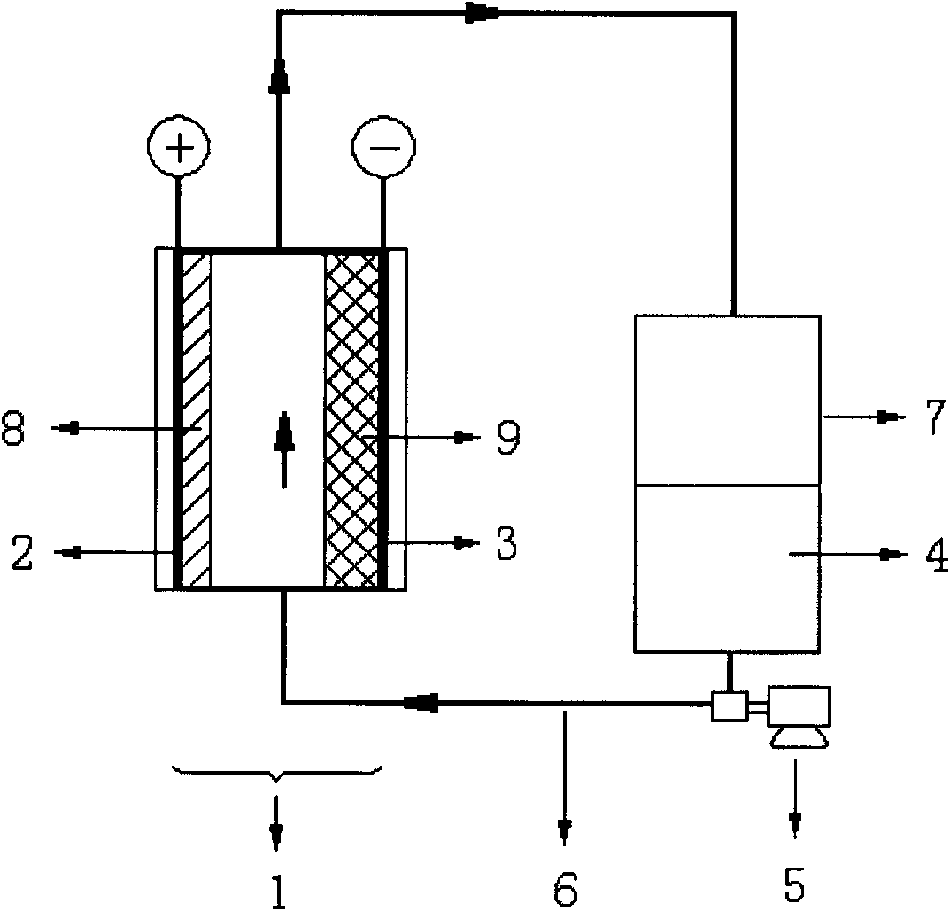
[0020] Such as figure 1 A 3mm thick high-density graphite plate is used as the positive electrode collector and the negative electrode collector are separated and fixed in the plastic case to form an all-lead flow battery monomer. The aqueous solution is stored in polyethylene tanks as the electrolyte, and a silicone tube is used as the pipeline, and a magnetic pump is used to push the electrolyte to flow across the opposite surfaces separating the positive and negative collectors. When charging, the divalent lead ions in the electrolyte are deposited as lead dioxide on the positive electrode collector, and as metallic lead on the negative electrode collector. When discharging, the lead dioxide and metallic lead dissolve into divalent lead ions and enter the electrolyte. at 20mA / cm 2 The current density can be charged and discharged, the current efficiency can reach more than 95%, and the energy efficiency is about 82%.

Embodiment 2

[0022] Such as figure 1 , 0.1mm thick tantalum foil with tantalum carbide film on the surface is used as the positive electrode collector, 0.1mm thick stainless steel foil is used as the negative electrode collector, the positive electrode collector and the negative electrode collector are separated and fixed in the plastic case to form an all-lead flow battery cell . An aqueous solution of 1.0 moles per liter of lead tetrafluoroborate and 1.0 moles per liter of tetrafluoroboric acid is stored in a polyethylene tank as the electrolyte, and a rubber hose is used as a pipeline, and a magnetic pump is used to push the electrolyte to flow through the positive collector and the negative collector Separate opposing surfaces. at 40mA / cm 2 The current density can be charged and discharged, the current efficiency can reach more than 98%, and the energy efficiency is about 75%.

Embodiment 3

[0024] Such as figure 1 A 0.1mm thick titanium foil with a titanium nitride film on its surface is used as the positive electrode collector, and a 0.1mm thick steel foil is used as the negative electrode collector. The positive electrode collector and the negative electrode collector are separated and fixed in a plastic case to form an all-lead flow battery cell body. The aqueous solution of 1.0 moles per liter of lead tetrafluoroborate and 1.5 moles per liter of tetrafluoroboric acid is stored in a polyethylene tank as the electrolyte, and the rubber hose is used as the pipeline, and a magnetic pump is used to push the electrolyte to flow through the positive collector and the negative collector. Separate opposing surfaces. at 10mA / cm 2 The current density can be charged and discharged, the current efficiency can reach more than 98%, and the energy efficiency is about 85%.


PUM


Abstract

The invention belongs to the electrochemical engineering and industrial fields, particularly to a lead liquid flow battery. The single battery cell consists of a deposition-type lead dioxide anode, a deposition-type lead dioxide cathode and an electrolyte containing soluble lead salt. A galvanic pile can be formed by a plurality of battery cells being connected serially or in parallel. The electrolyte of the galvanic pile is stored in a storage tank and the electrolyte pushed by a liquid pump keeps flowing between the storage tank and the pile pipes in the process of charging and discharging. The lead in the electrolyte is deposited on current collectors of the positive electrode and the negative electrode to become the lead dioxide and metallic lead when the battery is charged. And the lead dioxide and metallic lead dissolve in the electrolyte to become lead ions when the battery is discharged. The liquid flow battery is characterized by simple manufacture, low cost and long cycle life.

Description

technical field [0001] The invention belongs to the field of electrochemical engineering and industrial devices, in particular to an all-lead liquid flow battery in the technical field of battery production, which is used for simple and convenient construction of an all-lead liquid flow battery. Background technique [0002] Nowadays, energy has become an important basis for social development, while fossil energy is facing depletion. Vigorously developing renewable energy such as wind energy and solar energy is an important way to achieve sustainable energy development in my country. Renewable energy generation has time difference and instability, which limits its large-scale grid-connected utilization. Electricity storage is an effective method to solve the instability problem of renewable energy, which can realize the large-scale application of renewable energy. [0003] Among the chemical storage batteries, the flow battery (Flow cell, Flow battery) currently under dev...

Claims


Application Information

Patent Timeline
IPC IPC(8): H01M8/18H01M8/02H01M8/0202
CPCY02E60/528Y02E60/50
Inventor 程杰文越华刘东阳徐艳曹高萍杨裕生
Owner NO 63971 TROOPS PLA
Why Eureka
Try Eureka