Liquid phase hydrogenation method

A liquid-phase hydrogenation and hydrogenation reactor technology, which is applied in the field of hydrocarbon oil hydrogenation, can solve the problems of large investment and energy consumption, and achieve the effects of less equipment investment, less catalyst consumption, and low operating costs

Inactive Publication Date: 2012-10-17
CHINA PETROLEUM & CHEM CORP +1
View PDF4 Cites 20 Cited by
  • Summary
  • Abstract
  • Description
  • Claims
  • Application Information

AI Technical Summary

Problems solved by technology

DuPont's full liquid phase hydrogenation--DuPont DuPont was published on Docin.com (http://www.docin.com) TM clean fuel technology, from which Iso As can be seen in Figure 2 of the reactor system, the heating furnace is set

Method used


Image

  • Liquid phase hydrogenation method

Examples


Embodiment Construction

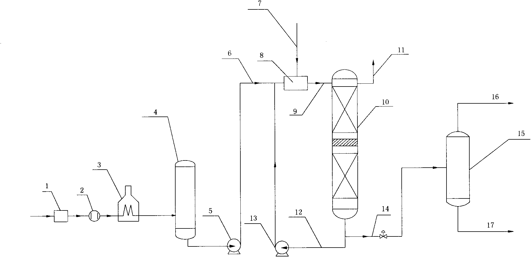
[0040] like figure 1As shown, the reactor shown in the figure is a two-stage catalyst bed. The feedstock oil (straight-run diesel oil) passes through the feedstock oil filter 1 to remove particles in the feedstock oil, then heats up to 330°C through the heat exchanger 2, and then enters the reaction feed heating furnace 3 to be heated to 380°C, and then enters the feedstock oil buffer tank 4. Send it to the mixing dissolver 8 through the hydrogenation feed pump 5, so that the fresh raw material oil 6, the cycle oil 12 and the hydrogen gas 7 are mixed in the mixing dissolver 8 to form a mixture flow 9, which enters the reactor 10, and is hydrogenated After the gas 11 is separated from the top of the reactor, the liquid is contacted with the catalyst to react, the gas is discharged from the top of the reactor, part of the reaction effluent is used as circulating oil 12, and the other part 14 enters the low-pressure separator 15 after being depressurized by the pressure reducing ...


PUM


Abstract

The invention discloses a liquid phase hydrogenation method. Raw oil (6) undergoes heat exchange by a heat exchanger (2) to the temperature of 260-360DEG C, enters a reaction feeding material heating furnace (3), is heated by the reaction feeding material heating furnace (3) to 280-400DEG C, is sent to a mixing dissolving machine (8) by a hydrogenation feeding material pump (5), and is mixed with cycle oil (12) and hydrogen (7) to form a mixture flow, the mixture flow enters a hydrogenation reactor (10), parts of the resulting reaction effluent are used as the cycle oil (12), and the other parts of the reaction effluent are separated. In the invention, the reaction feeding material heating furnace is replaced by a low pressure furnace, so the investment and operation cost is substantially reduced.

Description

technical field [0001] The invention relates to hydrocarbon oil hydrogenation technology, in particular to liquid phase hydrogenation technology. Background technique [0002] At present, the continuous development of the world economy and the increasingly stringent environmental protection regulations require the production of a large amount of light and clean fuels, which require the improvement and improvement of the existing refining technology to produce products that meet the requirements at the lowest cost. With the increasing shortage of crude oil resources and the development of heavy and inferior crude oil resources, catalytic cracking and coking have become important means of producing light fuel products, but the quality of products obtained by these two processes is generally difficult to meet the strict quality index requirements. In the quality system of light fuel products, sulfur content is the most important indicator. How to reduce the sulfur content in pe...

Claims


Application Information

Patent Timeline
IPC IPC(8): C10G67/02C10G67/14
Inventor 朱华兴张光黎韩旭辉刘兵兵薛皓师敬伟曾茜
Owner CHINA PETROLEUM & CHEM CORP
Why Eureka
Try Eureka