Method and device for purifying graphite

A technology of graphite and furnace body, applied in the field of high-purity purification of natural graphite, can solve the problems of huge investment, expensive equipment and low thermal efficiency, and achieve the effects of high heat utilization rate, novel process and simple device

Inactive Publication Date: 2012-10-24
辽宁点石技术开发有限公司
View PDF4 Cites 24 Cited by
  • Summary
  • Abstract
  • Description
  • Claims
  • Application Information

AI Technical Summary

Problems solved by technology

Although the high-temperature method can produce more than 99.99% of ultra-high-purity graphite, due to the extremely high calcination temperature, a high-temperature furnace must be specially designed and built. The equipment is expensive, the investment is huge, and the requirements for electric heating technology are strict. When the temperature rises to 450°C, it begins to be oxidized. The higher the temperature, the

Method used


Image

  • Method and device for purifying graphite

Examples


Embodiment 1

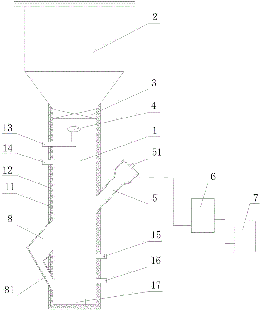
[0029] Embodiment 1, refer to figure 1 as shown,

[0030] A method for purifying graphite, it comprises the steps:

[0031] 1) Preparation of the device for purifying graphite;

[0032]2) Isolate the air: close the flash valve 3, the intake valve on the jet pipe 13, the tail gas discharge port 14 and the protective gas inlet 15, and load graphite raw materials into the hopper 2 (in order to improve the purification efficiency, generally use carbon mass Graphite concentrate with content ≥ 90% as raw material), connect the vacuum pump to the vacuum connection port 16, start the vacuum pump to pump the furnace body 1 into a vacuum state (vacuum degree is 0.01 ~ 0.05MPa), after the vacuum is completed, go to The protective gas inlet 15 is connected to the protective gas to restore the pressure in the furnace body 1 to atmospheric pressure, and the protective gas inlet 15 is closed after completion; in order to ensure the non-oxidizing atmosphere in the furnace, it can be evacuat...

Embodiment 2

[0045] It is basically the same as Example 1, the difference is: in order to obtain higher purity graphite, repeat steps 2) to 4) to perform a purification [return the purified graphite to the hopper 2 and enter the furnace body 1 again, that is After a second purification]. Graphite with an initial carbon mass content of 90% and a particle size of 100 mesh has a carbon mass content of 98.7% after the first purification; and a carbon mass content of 99.5% after the second purification.

Embodiment 3

[0047] It is basically the same as Example 1, except that in order to obtain graphite with higher purity, repeat steps 2) to 4) for secondary purification [return the purified graphite to the hopper 2 and enter the furnace body 1 again, Namely after the third purification]. Graphite with an initial carbon mass content of 90% and a particle size of 100 mesh has a carbon mass content of 98.7% after the first purification; a carbon mass content of 99.5% after the second purification; and a carbon content of 99.9% after the third purification.


PUM

PropertyMeasurementUnit
Granularityaaaaaaaaaa

Abstract

The invention belongs to the technical field of graphite purification, and particularly relates to a method and a device for high-purity purification of natural graphite. The method for purifying graphite is characterized by including the steps: 1) preparing a device for purifying graphite; 2) isolating the air; 3) generating high-temperature plasma flame flows, namely loading working gas to a working gas inlet of a plasma torch, and starting the plasma torch to enable the working gas to be connected by ionization puncture to eject high-temperature plasma flame flows from the plasma torch; and 4) using the high-temperature plasma flame flows to purify graphite, namely turning on a flash valve, feeding gas into a gas injection pipe, enabling graphite raw materials to fall into the bottom of a furnace via the high-temperature plasma flame flows to obtain purified graphite, and opening a taking port to take out the purified graphite after the furnace is cooled, wherein a gas inlet valve on the gas injection pipe is in linkage with the flash valve. The method is low in energy consumption, the graphite obtained by the method is high in purity, and the device is simple.

Description

technical field [0001] The invention belongs to the technical field of graphite purification, and in particular relates to a method and a device for high-purity purification of natural graphite. Background technique [0002] Graphite is a highly crystalline carbon material, which is widely used in metallurgy, machinery, chemical industry, refractory, electronics, military, In the fields of aerospace and nuclear energy, it has become an indispensable non-metallic material for the development of modern industry and high, new and cutting-edge technologies. [0003] With the continuous development of technology, the flaky high-carbon graphite products obtained through the beneficiation process can no longer meet the requirements of some high-tech industries, so it is necessary to further improve the purity of graphite. At present, the methods for purifying graphite at home and abroad mainly include flotation method, acid-base method, hydrofluoric acid method, chlorination roast...

Claims


Application Information

Patent Timeline
IPC IPC(8): C01B31/04C01B32/215
CPCY02P20/10
Inventor 曹宏鲍世聪薛俊李先福
Owner 辽宁点石技术开发有限公司
Why Eureka
Try Eureka