Polycrystalline silicon production process and production system used for same

A production process, polysilicon technology, applied in the direction of silicon compounds, inorganic chemistry, non-metallic elements, etc., can solve the problems of increased metal impurity precipitation, damage, high temperature in the center of silicon rods, etc., to achieve the effect of increasing supersaturation and preventing cauliflower material

Active Publication Date: 2012-10-24
巴彦淖尔聚光硅业有限公司
View PDF3 Cites 6 Cited by
  • Summary
  • Abstract
  • Description
  • Claims
  • Application Information

AI Technical Summary

Problems solved by technology

Which attached image 3 The disadvantage of the a process flow in the process is that the main furnace is charged. In the later stage of production, the ratio of other gases except trichlorosilane to trichlorosilane in the reduction tail gas is 9~6:1, and the ratio of trichlorosilane If the supersaturation is too low to meet the growth needs of the auxiliary furnace, cauliflower material will appear on the surface of the polysilicon rod of the auxiliary furnace, and the gap between the cauliflower material will greatly increase the precipitation of B, P and metal impurities due to the high temperature. Ultimately, the quality of polysilicon in the auxiliary furnace is seriously unqualified
attached Figure 4 The disadvantage of the b process in the process is that the feed to the auxiliary furnace is twice that of the main furnace. Too much feed will reduce the surface temperature of the auxiliary furnace, and the reaction temperature on the polysilicon surface must be maintained during operation. Therefore, in In the middle stage of the growth of the auxiliary furnace, there will be a large increase in current in order for the surface temperature of the silicon rod to reach the normal reaction temperature, which will cause the center temperature of the silicon rod to be too high, and eventually the melting core of the silicon rod will cause the rod to fall. If it is not handled properly, the reduction furnace will be damaged. A series of vicious accidents, so this method lacks operability
[0004] The invention patent application with the patent publication number CN101541678A discloses a process for producing polysilicon using a fluidized bed reactor and a Siemens reactor, and the exhaust gas from the Siemens reactor is fed to the fluidized bed reaction as a feed gas In the device, this process relatively improves the primary utilization rate of trichlorosilane, reduces the heat required to be supplied by the fluidized bed, and the feed gas flow supplemented to the fluidized bed can also meet the needs of the continuous operation of the fluidized bed, but due to The surface area of ​​granular silicon is large, and it is easy to cause pollution of polysilicon particles during the production process, such as the pollution of heavy metal elements on the furnace wall. Therefore, the polysilicon produced in the fluidized bed cannot meet the standard of electronic grade polysilicon; the abrasion of solid particles and the entrainment of dust in the airflow Emission in the exhaust gas will not only affect the exhaust gas recovery system, but also increase the exhaust gas filtration and recovery equipment, and cause the loss of raw materials

Method used


Image

  • Polycrystalline silicon production process and production system used for same
  • Polycrystalline silicon production process and production system used for same
  • Polycrystalline silicon production process and production system used for same

Examples


Embodiment 1

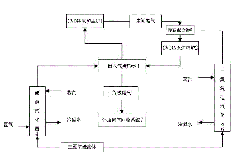
[0035] Such as figure 1 As shown, refined trichlorosilane and hydrogen are mixed in the bubbling vaporizer 4, and by controlling the pressure and temperature of the bubbling vaporizer 4, hydrogen and refined trichlorosilane are transported to the inlet and outlet gas at a molar ratio of 3:1. heat exchanger 3.

[0036] The mixed gas feed entering the inlet and outlet gas heat exchanger 3 is heat-exchanged with the high-temperature final tail gas from the auxiliary furnace 2 of the CVD reduction furnace, which not only increases the feed temperature but also reduces the final tail gas temperature.

[0037] After the mixed gas feed is heated by the final exhaust gas from the auxiliary furnace 2 of the CVD reduction furnace, it continues to enter the main furnace 1 of the CVD reduction furnace, and reacts on the surface of the silicon core at 1150 °C in the main furnace 1 of the CVD reduction furnace to form polysilicon.

[0038] The by-product of the main furnace 1 of the CVD red...

Embodiment 2

[0042] Such as figure 1 As shown, refined trichlorosilane and hydrogen are mixed in the bubbling vaporizer 4, and by controlling the pressure and temperature of the bubbling vaporizer 4, hydrogen and refined trichlorosilane are delivered to the inlet and outlet gas at a molar ratio of 4:1. heat exchanger 3.

[0043] The mixed gas feed entering the inlet and outlet gas heat exchanger 3 is heat-exchanged with the high-temperature final tail gas from the auxiliary furnace 2 of the CVD reduction furnace, which not only increases the feed temperature but also reduces the final tail gas temperature.

[0044] After the mixed gas feed is heated by the final tail gas from the auxiliary furnace 2 of the CVD reduction furnace, it continues to enter the main furnace 1 of the CVD reduction furnace, and reacts on the surface of the silicon core at 1150°C in the main furnace to form polysilicon.

[0045] The by-product of the main furnace 1 of the CVD reduction furnace is used as the inter...

Embodiment 3

[0049] Such as figure 1 As shown, refined trichlorosilane and hydrogen are mixed in the bubbling vaporizer 4, and by controlling the pressure and temperature of the bubbling vaporizer 4, hydrogen and refined trichlorosilane are transported to the inlet and outlet gas at a molar ratio of 3.5:1. heat exchanger 3.

[0050] The mixed gas feed entering the inlet and outlet gas heat exchanger 3 is heat-exchanged with the high-temperature final tail gas from the auxiliary furnace 2 of the CVD reduction furnace, which not only increases the feed temperature but also reduces the final tail gas temperature.

[0051] After the mixed gas feed is heated by the final tail gas from the auxiliary furnace 2 of the CVD reduction furnace, it continues to enter the main furnace 1 of the CVD reduction furnace, and reacts on the surface of the silicon core at 1150°C in the main furnace to form polysilicon.

[0052] The by-product of the main furnace 1 of the CVD reduction furnace is used as the i...


PUM


Abstract

The invention relates to a polycrystalline silicon production process and a production system used for the same. The polycrystalline silicon production process comprises the following steps of: mixing fine trichlorosilane with the concentration of more than 99.99% and hydrogen in the mol ratio of the hydrogen to the fine trichlorosilane of (4-3):1 to be used as a mixed gas feeding material; introducing the mixed gas feeding material into a CVD (Chemical Vapor Deposition) reduction furnace, wherein the mixed gas feeding material sequentially passes through a bubble type gasifying device, a heat exchanger of an inlet / outlet device, and a main furnace of the CVD reduction furnace and an auxiliary furnace of the CVD reduction furnace which are connected in series; carrying out heat exchange on the final exhaust tail gas exhausted by the auxiliary furnace of the CVD reduction furnace and introducing the gas into the main furnace of the CVD reduction furnace to carry out reaction on the surface of a silicon core in the main furnace of the CVD reduction furnace to generate polycrystalline silicon, wherein a byproduct is middle tail gas; mixing the middle tail gas with the supplemented fine trichlorosilane gas and introducing the mixed gas into the auxiliary furnace of the CVD reduction furnace to react on the surface of the silicon core in the auxiliary furnace of the CVD reduction furnace to generate the polycrystalline silicon, wherein the byproduct is the final exhaust tail gas; and carrying out the heat exchange on the final exhaust tail gas which is discharged out of the furnace, and the mixed gas feeding material, and introducing into a reduction tail gas recycling system. The process and the production system disclosed by the invention can be used for manufacturing the high-quality electronic-grade polycrystalline silicon in a high-efficiency and low-cost manner.

Description

technical field [0001] The invention relates to a polysilicon production process and a production system used in the process. Background technique [0002] Most factories use the trichlorosilane method to produce polysilicon, that is, trichlorosilane and hydrogen are mixed in a certain ratio, and after heat exchange with the reduction tail gas, they enter the reduction furnace and react on the surface of the silicon core at 1150 ° C in the furnace to form polysilicon. , the by-product reduction tail gas exits the reduction furnace, heats the feed mixture gas, and then enters the subsequent tail gas recovery system (see attached figure 2 ). Although the yield of this method is not low, and the trichlorosilane, hydrogen, and silicon tetrachloride in the reduction tail gas can be recycled, the primary use efficiency of the trichlorosilane is very low, and the unreacted trichlorohydrogen in the reduction tail gas Silicon accounts for about 52-60% of the total trichlorosilane f...

Claims


Application Information

Patent Timeline
Patent Type & Authority Applications(China)
IPC IPC(8): C01B33/035
Inventor 齐林喜郭金强郝爱科张文奎朱涛邢仕益
Owner 巴彦淖尔聚光硅业有限公司
Why Eureka
Try Eureka