
Winding method of high-frequency transformer

A high-frequency transformer and winding method technology, applied in the field of transformers, can solve the problems of output winding voltage drift, difficult to control, poor coupling of secondary windings, etc., to achieve good electromagnetic coupling, improve performance, and solve the effects of voltage drift

Active Publication Date: 2014-01-22
DONGGUAN DAZHONG ELECTRONICS
View PDF5 Cites 0 Cited by
  • Summary
  • Abstract
  • Description
  • Claims
  • Application Information

AI Technical Summary

Problems solved by technology

[0004] In the prior art, a high-frequency transformer generally includes three secondary windings, and its winding method is three-wire parallel winding, and the layers are isolated with tape, which is called a multi-layer isolation winding method. This multi-layer isolation winding method, the secondary The coupling between the primary windings is poor, resulting in the application in the circuit, prone to output winding voltage drift (usually high voltage), difficult to control

Method used


Image

  • Winding method of high-frequency transformer
  • Winding method of high-frequency transformer

Examples


Embodiment 1

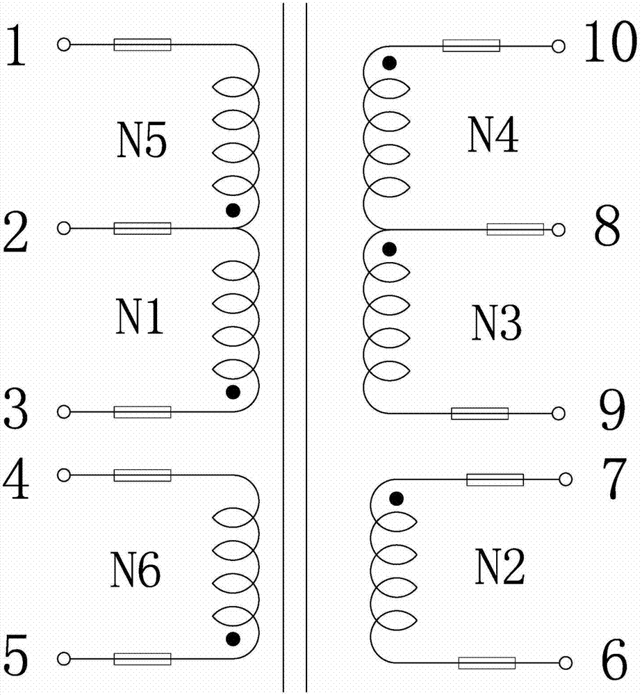
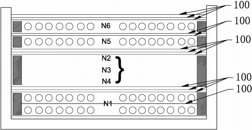
[0037] A winding method of a high-frequency transformer in this embodiment, the high-frequency transformer includes a skeleton, an iron core, a primary winding and a secondary winding, the iron core is arranged on the skeleton, and the primary winding and the secondary winding are all wound on the iron core, such as figure 1 and figure 2 As shown, the winding method of its secondary winding includes the following steps:

[0038] (1) The winding N2 starts two strands at the starting end 7 of the skeleton, the winding N3 starts one strand at the starting end 8 of the skeleton, and the winding N4 starts one strand at the starting end 10 of the skeleton;

[0039] (2) Twist the four strands of (1) into a twisted strand;

[0040] (3) After wrapping the twisted wire of (2) evenly and densely around the winding groove of the skeleton for three layers, hang the end of the strand of winding N3 on Hanging on the 8 ends of the starting line of the skeleton;

[0041] (4) Wind the two s...

Embodiment 2

[0047] A winding method for a high-frequency transformer. The other structures of this embodiment are the same as those of Embodiment 1, except that the primary winding includes winding N1, winding N5 and auxiliary winding N6, and the windings of the primary winding and the secondary winding are sequentially The sequence is winding N1, secondary winding, winding N5 and auxiliary winding N6.

[0048] The winding method between the primary winding and the secondary winding is called the sandwich winding method, which has the following advantages: 1. It can reduce the leakage inductance of the transformer, and the benefit of reducing the leakage inductance is that the voltage spike will be reduced, making the MOSFET (gold oxide Half field effect transistor Metal-Oxide-Semiconductor Field-Effect Transistor) voltage stress reduction;

[0049] 2. Improve EMI (electromagnetic interference): the common mode interference current caused by MOSFET and heat sink can also be reduced, there...


PUM

PropertyMeasurementUnit
diameteraaaaaaaaaa

Abstract

The invention relates to the technical field of transformers, in particular to a winding method of a high-frequency transformer. The winding method comprises the following steps of: (1) starting two strands for a winding N2 at a framework starting end 7, starting one strand for a winding N3 at a framework starting end 8, and starting one strand for a winding N4 at a framework starting end 10; (2) twisting four strands obtained in the step (1) into a strand of twisted wire; (3) uniformly and tightly winding the twisted wire obtained in the step (2) around a framework winding groove for three layers, hanging the tail end of a strand of wire of the winding N3 at a framework take-up end 9, and hanging the tail end of a strand of wire of the winding N4 at a framework starting end 8; and (4) winding two strands of wires of the winding N2 by one more circle, and hanging the tail ends of the two strands of wires at a framework take-up end 6. The winding method of a secondary winding is changed, so that the electromagnetic coupling among secondary windings can be improved, the phenomenon of voltage drift of secondary windings is avoided, and the performance of the high-frequency transformer is improved.

Description

technical field [0001] The invention belongs to the technical field of transformers, in particular to a winding method of a high-frequency transformer. Background technique [0002] The function of the power transformer is power transmission, voltage conversion and insulation isolation. As a main soft magnetic electromagnetic component, it is widely used in power supply technology and power electronics technology. [0003] The high-frequency transformer is the most important component of the switching power supply. High-frequency transformer is a power transformer whose operating frequency exceeds intermediate frequency (10kHz). It is mainly used as a high-frequency switching power transformer in high-frequency switching power supplies, and is also used as a high-frequency inverter in high-frequency inverter power supplies and high-frequency inverter welding machines. power transformer. [0004] In the prior art, a high-frequency transformer generally includes three secon...

Claims


Application Information

Patent Timeline
Patent Type & Authority Patents(China)
IPC IPC(8): H01F41/06H01F27/30H01F41/12H01F27/32
Inventor 李正中丁玉山
Owner DONGGUAN DAZHONG ELECTRONICS
Learn More