Coplanar compact type photonic crystal GPS (Global Positioning System) receiving antenna

A photonic crystal and receiving antenna technology, applied in the antenna grounding device, radiating element structure and other directions, can solve the problems of affecting the antenna pattern, low gain, increased back lobe, etc., to increase electromagnetic wave radiation power, improve efficiency, improve performance effect

Inactive Publication Date: 2012-11-28
CHINA ZHENHUA GRP YUNKE ELECTRONICS
View PDF3 Cites 3 Cited by
  • Summary
  • Abstract
  • Description
  • Claims
  • Application Information

AI Technical Summary

Problems solved by technology

But it also has defects. For example, the structure of the patch antenna can support surface waves, and the existence of surface waves in the patch antenna makes the energy trapped near the dielectric layer and cannot radiate out, which reduces the efficiency of the antenna. At the truncation of the medium, the electromagnetic wave will radiate and diffract, which will affect the antenna pattern, mainly causing the increase of the back lobe and the increase of the side lobe fluctuation, making the antenna vulnerable to electronic interference and deception
Due to the influence of surface waves, high-order modes, feeder loss and dielectric loss, patch antennas have disadvantages such as low efficiency, narrow bandwidth, and low gain.
These shortcomings affect the application of the patch antenna to a certain extent, therefore, it is urgent to improve it for better application

Method used


Image

  • Coplanar compact type photonic crystal GPS (Global Positioning System) receiving antenna
  • Coplanar compact type photonic crystal GPS (Global Positioning System) receiving antenna
  • Coplanar compact type photonic crystal GPS (Global Positioning System) receiving antenna

Examples


Embodiment Construction

[0012] The invention will be further described below in conjunction with the drawings, but not limited to the embodiments.

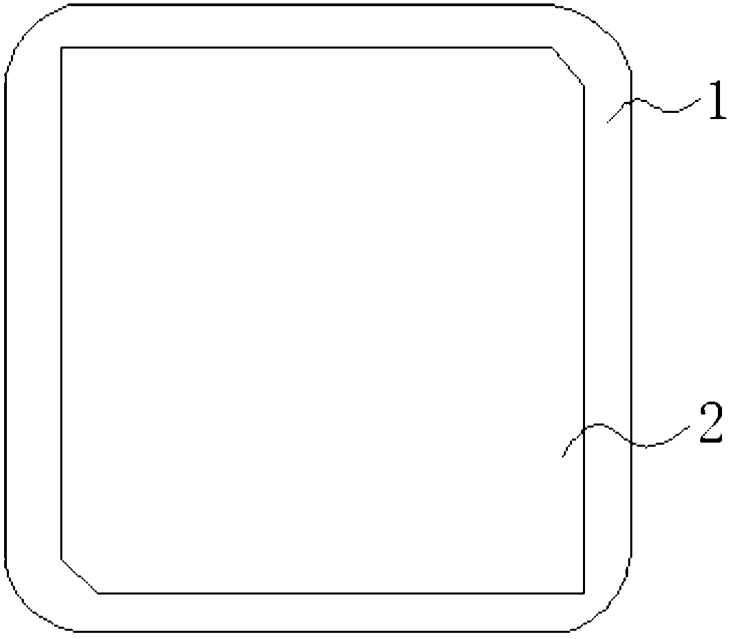
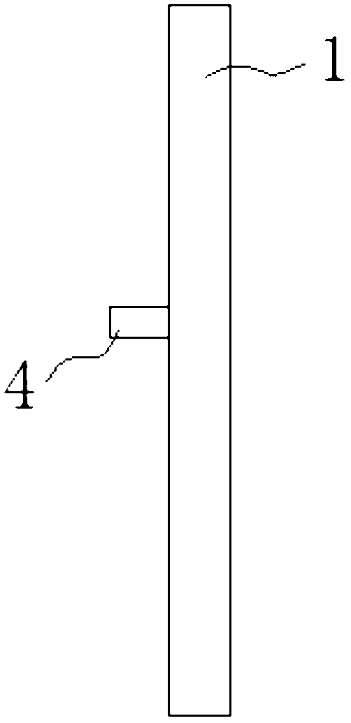
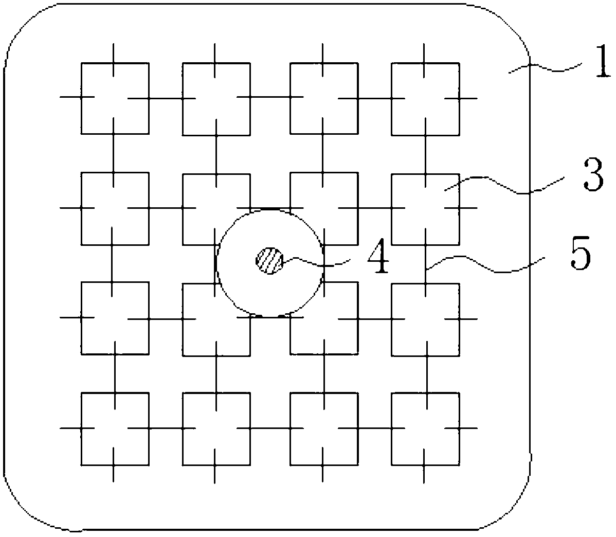
[0013] Such as figure 1 , figure 2 , image 3 As shown, a coplanar compact photonic crystal GPS receiving antenna includes a dielectric substrate 1, a patch antenna 2 is provided on the front of the dielectric substrate 1, a ground plate is provided on the back of the dielectric substrate 1, a feed pin 4 is provided in the center of the ground plate, and a ground plate A periodically distributed photonic crystal structure is set on it.

[0014] Each photonic crystal structure unit is composed of a square patch 3 and an inductor wire 5 inserted in the middle, and adjacent photonic crystal structure units are connected by the inductor wire 5.

[0015] A two-dimensional periodically distributed photonic crystal structure unit is formed on an ordinary ceramic dielectric GPS receiving antenna by etching or silk-screening. The gap between adjacent units provides co...


PUM


Abstract

The invention discloses a coplanar compact type photonic crystal GPS (Global Positioning System) receiving antenna which comprises a dielectric substrate, a patch antenna is arranged on the front face of the dielectric substrate, an earth plate is arranged on the back face of the dielectric substrate, a feed pin is arranged in the center of the earth plate, photonic crystal structures are periodically distributed on the earth plate, each photonic crystal structure unit comprises a square patch and an inductance wire inserted in the middle, and the adjacent photonic crystal structure units are connected via the inductance wire. In the invention, a coplanar compact type photonic crystal is introduced into the earth plate of the patch antenna, the forbidden effect of photonic crystal is utilized, surface waves propagating along a base plate medium are inhibited, the electromagnetic wave radiation power of the antenna coupled to the space is increased, the inhibition of the surface waves can increase the efficiency of the antenna, and the performance of the antenna is improved.

Description

Technical field [0001] The invention belongs to the technical field of photonic crystal applications, and specifically relates to a coplanar compact photonic crystal GPS receiving antenna. Background technique [0002] The concept of photonic crystals was independently proposed by Eli Yablonovitch and Sajeev John in 1987. Photonic crystals are a new type of artificial material with periodic spatial permittivity changes, lattice constants comparable to light wavelengths, and a photonic band gap structure that can control the propagation state of photons. The basic feature of photonic crystals is that they have a photonic band gap. Electromagnetic waves whose frequencies fall within the band gap are prohibited from spreading. Another main feature of photonic crystals is photonic localization. If impurities or defects are introduced into the periodic structure of the photonic crystal, the photons matching the defect state frequency will be localized at the defect position. The ph...

Claims


Application Information

Patent Timeline
Patent Type & Authority Applications(China)
IPC IPC(8): H01Q1/48H01Q1/38
Inventor 李胜刘剑林罗彦军李吉云罗向阳谢强张青周瑞山阳元江韩玉成
Owner CHINA ZHENHUA GRP YUNKE ELECTRONICS
Why Eureka
Try Eureka