Method and device for spray forming of high-speed solid phase particles
A solid-phase particle, injection molding technology, applied in the field of devices implementing the technology, can solve the problems of single injection molding form, low gas outlet velocity of atomizing nozzle, dispersion of metal liquid, limited cooling acceleration effect, etc., and achieve stable performance, The effect of the equipment structure is separate and easy to promote and use
- Summary
- Abstract
- Description
- Claims
- Application Information
AI Technical Summary
Problems solved by technology
Method used
Image
Examples
specific Embodiment 1
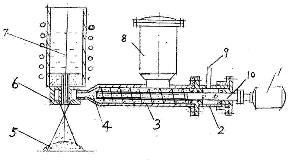
[0059] This embodiment provides a high-speed solid-phase particle injection molding device. as attached figure 1 As shown, the high-speed solid-phase particle injection molding device includes: high-speed solid-phase particle generating equipment and an induction melting furnace containing molten metal.
[0060] The high-speed solid-phase particle generating equipment includes: motor 1; gas reversing chamber 2; material pipe 3; conical pipe 4; solid-liquid phase particle deposit 5; nozzle 6; induction melting furnace 7; powder bin 8; Tube 9; stainless steel gas tube 10.
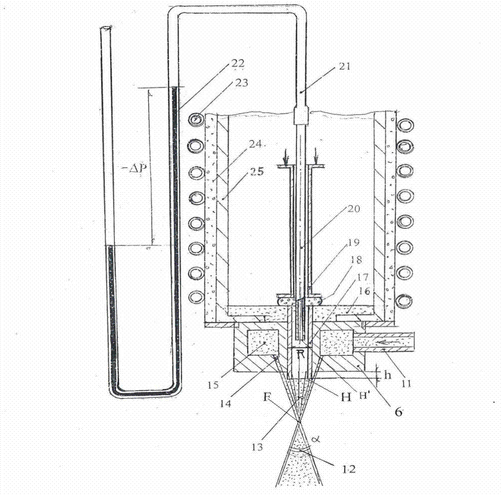
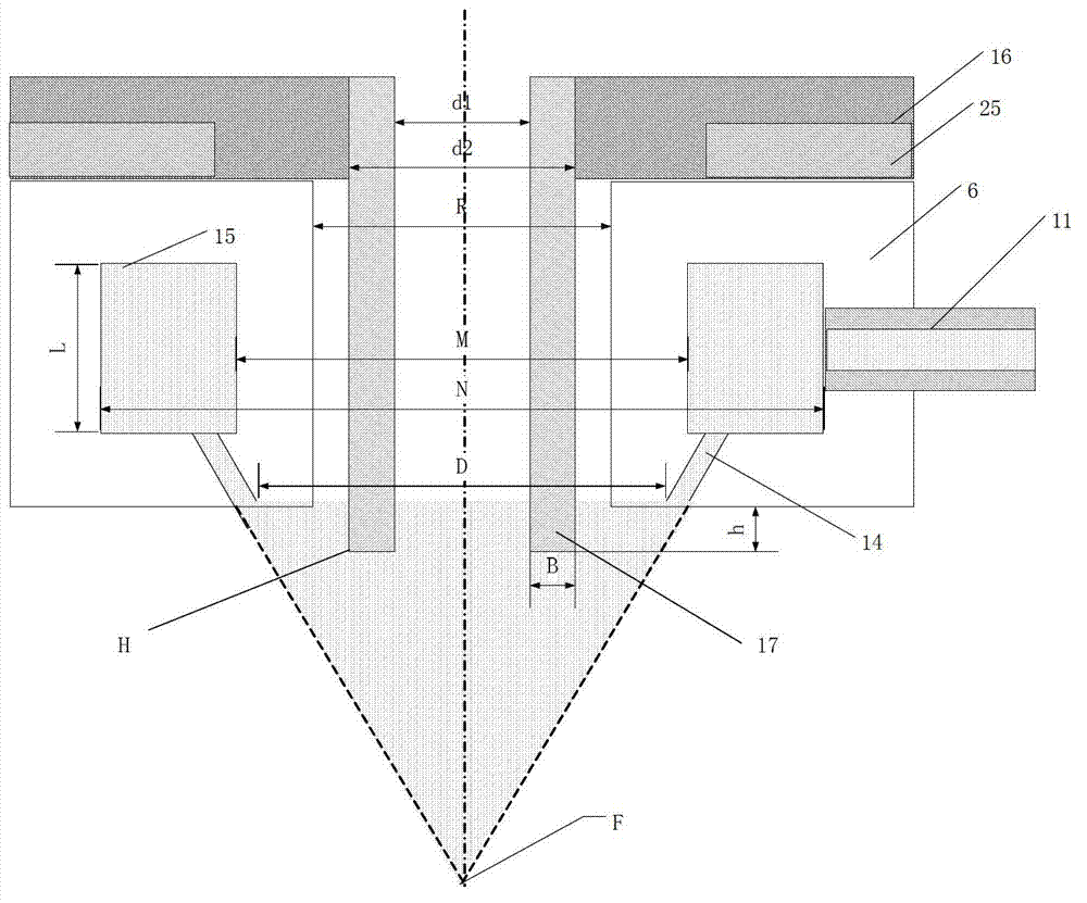
[0061] as attached figure 2 As shown, the induction melting furnace includes: melting crucible bottom 16; molten metal delivery conduit 17; high (medium) frequency induction coil 23; For the heat preservation of the metal liquid flow in the furnace, and the insulation between the crucible and the induction coil, a layer (MgO+MgCl 6 ) drying the self-setting refractory insulation layer (thickness 8-12 mm)...
specific Embodiment 2
[0071] This embodiment provides a method for performing high-speed solid-phase particle injection molding using the high-speed solid-phase particle injection molding device of the first embodiment.
[0072] The working mode of the high-speed solid-phase particle injection molding is as follows:
[0073] Step 1, the motor 1 drives the stainless steel gas pipe 10 to rotate axially;
[0074] Step 2, adding solid powder from the powder silo 8 to the material tube 3, and the solid powder is pushed into the conical tube 4 through the screw pusher blade installed on the surface of the stainless steel air tube;
[0075] Step 3, the high-pressure gas introduced from the high-pressure gas introduction pipe 9 into the gas reversing chamber 2 enters the inside of the stainless steel gas pipe 10 through the small hole on the surface of the stainless steel gas pipe 10, and is ejected from the front end of the stainless steel gas pipe 10, and the ejected high-pressure gas A negative pressur...
specific Embodiment 3
[0082] The preparation method of the high-speed solid-phase particle jet deposition equipment in specific embodiment one is as follows:
[0083] Step 1, preparation of high-speed solid-phase particle generator
[0084] In step 1.1, the engine type is determined according to the spray deposition rate and the composition of the spray deposition alloy to be prepared.
[0085] According to the spray deposition speed and the composition of the spray deposition alloy to be prepared (the composition of the composite material of metal and solid phase particles to be prepared), the required high-speed solid phase particle supply speed is obtained, and according to this supply speed, set to meet this requirement 1. The powder propulsion equipment required by the technical requirements, that is, the electric motor.
[0086] Step 1.2, setting the inclination angle of the screw pusher blade.
[0087] The inclination angle of the screw pusher blade is related to the speed at which the solid...
PUM
| Property | Measurement | Unit |
|---|---|---|
| Wall thickness | aaaaa | aaaaa |
| Diameter | aaaaa | aaaaa |
Abstract
Description
Claims
Application Information
 - R&D
- Intellectual Property
- Life Sciences
- Materials
- Tech Scout
- Unparalleled Data Quality
- Higher Quality Content
- 60% Fewer Hallucinations
Browse by: Latest US Patents, China's latest patents, Technical Efficacy Thesaurus, Application Domain, Technology Topic, Popular Technical Reports.
© 2025 PatSnap. All rights reserved.Legal|Privacy policy|Modern Slavery Act Transparency Statement|Sitemap|About US| Contact US: help@patsnap.com


