
Laser pulse electroplating system

A laser pulse and pulse electroplating technology, which is applied in the field of laser pulse electroplating systems, can solve the problems of not being able to obtain a positive square wave, a large degree of waveform distortion, and low frequency, and achieve high-precision controllable deposition, absorption, and precise control.

Active Publication Date: 2012-12-12
INST OF SEMICONDUCTORS - CHINESE ACAD OF SCI
View PDF5 Cites 7 Cited by
  • Summary
  • Abstract
  • Description
  • Claims
  • Application Information

AI Technical Summary

Problems solved by technology

However, when the pulse electroplating power supply is used for electroplating, it cannot obtain an ideal square wave, but a waveform similar to a trapezoid, which will affect the full play of the beneficial effect of the instantaneous high potential of pulse electroplating.
The pulse frequency will also have a great impact on the crystallization of the coating. If the frequency is too low, the effect will not be obvious; if the frequency is too high, the waveform distortion will be large, and even the pulse current will become a DC current.
The main reason is that when a pulse electroplating power supply with a high frequency is used, the front and rear edges of the pulse can easily have a serious impact on the turn-on and turn-off time, thereby affecting the full play of the beneficial effect of the instantaneous high potential of pulse electroplating

Method used


Image

  • Laser pulse electroplating system
  • Laser pulse electroplating system
  • Laser pulse electroplating system

Examples


Embodiment

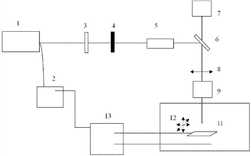
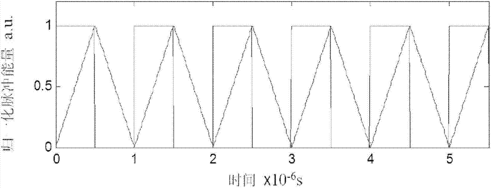
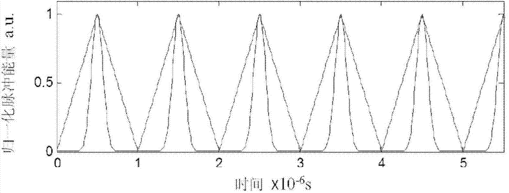
[0040] The following combination figure 1 The specific implementation of the laser pulse electroplating system of the present invention is described in detail: pulse laser 1 is that the laser beam wavelength of Q-switched YAG frequency doubled laser output is 532nm, and average power is 350mW, and pulse width is 100ns, and spot diameter after focusing is 500um, The working frequency is 1MHz; the pulse laser 1 and the pulse electroplating power supply 13 are connected to the pulse generation controller 2, and the pulse laser emitted by the pulse laser 1 and the power pulse sent by the pulse electroplating power supply 13 are controlled to be superimposed by the method of electrical signal modulation, and the instant delay difference is 0. The repetition frequency of the pulsed laser and the pulsed electroplating power supply must be consistent. A schematic comparison of ideal power pulses and actual power pulses is shown in Figure 2(a). Among them, the ideal power pulse (hori...


PUM


Abstract

The invention discloses a laser pulse electroplating system. The laser pulse electroplating system comprises a pulse laser, a pulse generation controller, an attenuator, an electronic shutter, a beam expander, a reflected mirror, a charge coupled device (CCD) real-time monitoring system, an optical vibrating mirror, a focusing lens, an electrolytic tank, a three-dimensional moving table and a pulse electroplating power supply. The pulse electroplating power supply and the pulse laser are adopted, the beyond of the performance of the high-frequency pulse electroplating power supply is limited, and laser pulse of the pulse laser which is controlled to send is matched with electronic pulse sent by the pulse electroplating power supply, so that the processing efficiency and the resolution ratio of a plating layer are improved. The application field comprises laser electroplating and laser etching.

Description

technical field [0001] The invention relates to the technical field of laser electroplating, in particular to a laser pulse electroplating system, which realizes the thermal effect of metal ions on the laser by utilizing the combined effect of laser pulse and pulse electroplating power supply, combined with the crystal nucleus growth characteristics of the material to be processed and the electrolyte Full absorption, high precision and controllable deposition on the cathode, in order to facilitate the achievement of ideal electroplating treatment results. Background technique [0002] Pulse electroplating is a powerful means to improve the quality of the coating through the control method outside the tank. Compared with the ordinary DC electroplating coating, it has more excellent properties, such as corrosion resistance, wear resistance, high purity, electrical conductivity, welding and anti-corrosion. It has good discoloration performance, and can greatly save rare and pre...

Claims


Application Information

Patent Timeline
IPC IPC(8): C25D5/00C25D5/18
Inventor 杨盈莹林学春于海娟
Owner INST OF SEMICONDUCTORS - CHINESE ACAD OF SCI
Learn More