Convertor coal gas recovery method

A recovery method and converter gas technology, applied in separation methods, chemical instruments and methods, gas dust removal, etc., can solve problems such as water waste, achieve the effects of improving quality, reducing anti-corrosion requirements, and reducing initial investment and operating costs

Active Publication Date: 2012-12-19
SHANDONG PROVINCE METALLURGICAL ENG CO LTD
View PDF6 Cites 4 Cited by
  • Summary
  • Abstract
  • Description
  • Claims
  • Application Information

AI Technical Summary

Problems solved by technology

[0010] 1. Change the converter flue gas at about 850°C from the flue heat exchange device from vaporization cooling to heat exchange with the heat exchange device. On the one hand, the problem of water waste must be solved, and on the other hand, the physical properties of the converter flue gas must be realized. Effective use of sensible heat to achieve the effect of killing two birds with one stone

Method used


Image

  • Convertor coal gas recovery method
  • Convertor coal gas recovery method

Examples


Embodiment 1

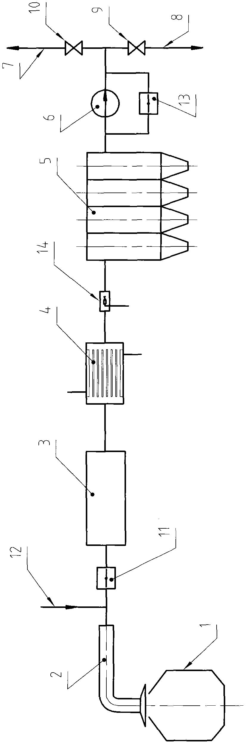
[0034] Example 1, such as figure 1 Shown.

[0035] in figure 1 Among them, 1 is the converter. 2 is the flue heat exchange device of the converter. 3 is a combined device that has the functions of coarse dust removal, heat storage and combustion chamber (for the convenience of ash discharging, if necessary, it can be arranged in parallel with two, one is prepared and the other is used, so as not to affect the converter production). 4 is a heat exchange device. Specifically, it uses a fire tube heat exchange device or a fire tube boiler, and it is recommended to install it vertically to avoid or reduce dust accumulation. 5 is a fine dust removal device, specifically, it is a bag filter. 6 is the fan. 7 is the recovery channel of converter gas. 8 is the combustion and release channel of converter gas to facilitate emergency and / or release of residual gas that has no recovery value. 9 and 10 are control valves arranged on the release channel 8 and the recovery channel 7 res...

Embodiment 2

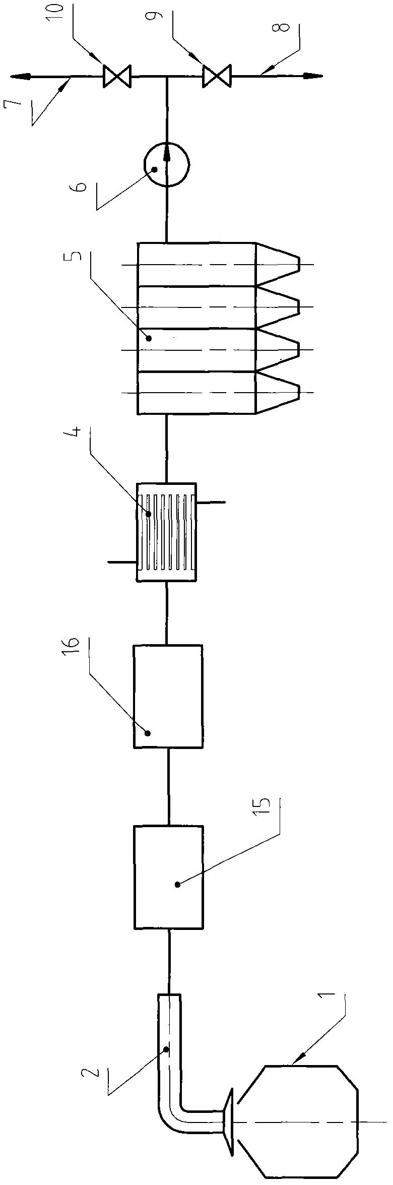
[0058] Example 2, such as figure 2 Shown.

[0059] This embodiment is a simplification of Embodiment 1.

[0060] Compared with Embodiment 1, it eliminates the combination device 3, the on-off valve 11, the inert gas input channel 12, the return on-off valve 13 of the fan 6 and the water mist generator 14; and uses a newly-added separate coarse dust collector 15 And a separate combustion chamber 16 instead of the combined device 3. The separate coarse dust collector 15 and the separate combustion chamber 16 are preferably added with the function of heat storage in order to obtain a better use effect.

[0061] The working process of this embodiment is: the converter flue gas discharged from the flue heat exchange device 2 first enters the separate coarse dust collector 15 for preliminary dust removal, and keeps it at a higher temperature, and can carry out gas and oxygen in it. Then, the flue gas enters the separate combustion chamber 16, and continues the process of the reaction of ...


PUM


Abstract

The invention relates to a convertor coal gas recovery method, and belongs to the technical field of recycling physical sensible heat in convertor flue gas. The main technical problems to be solved are as follows: on one hand, the water waste problem is to be solved, on the other hand, efficient utilization of physical sensible heat in the convertor flue gas is to be realized, and the problems of sensibility increase of confined explosion caused by due to cancel of an evaporation cooling process and the like are also to be solved. The method comprises allocation of a flue heat exchange device, a rough dust removing device and a refined dust removing device, an induced draft fan, a pipe network a control system, and is characterized in that a combustion chamber is arranged in the method, a heat exchanger is also arranged in the method and the heat exchanger is installed behind the combustion chamber. The method is suitable for the technical field of recycling physical sensible heat in the convertor flue gas, and has the characteristics of saving water, saving energy, improving system safety, improving recovery rate of convertor coal gas and the like.

Description

Technical field [0001] The invention relates to a method for recovering converter gas, belonging to the technical field of recovering and utilizing physical sensible heat in converter flue gas. Background technique [0002] The converter gas recovery system is one of the energy recovery processes widely used in the current metallurgical industry. Its main process system includes flue heat exchange device, cooling device, coarse and fine dust removal device, induced draft fan, switching station, pipe network setting and control system equipment. The cooling device used in the existing system is a vaporization cooling tower, and the fine dust removal device used is an electric precipitator. [0003] The main problems of the existing system are: [0004] 1. The physical sensible heat in the converter flue gas is all wasted in the process of vaporization and cooling. Because the flue gas volume of the converter is very large, this waste is amazing. [0005] 2. In the vaporization coolin...

Claims


Application Information

Patent Timeline
Patent Type & Authority Applications(China)
IPC IPC(8): C21C5/38C10K1/02B01D46/02
CPCY02P20/10
Inventor 黄东生钱纲李希昌盛振江刘鹏云贠汝平
Owner SHANDONG PROVINCE METALLURGICAL ENG CO LTD
Why Eureka
Try Eureka