CMOS (complementary metal-oxide semiconductor transistor) biomedical signal acquisition unit in differential capacitance network feedback structure

A technology of signal collector and differential capacitance, which is applied in the field of CMOS biomedical signal collector with feedback structure of differential capacitance network, can solve the problem of unsuitable for implantable in vivo signal detection, difficult to achieve high-precision matching, power consumption and noise Large and other problems, to achieve the effect of easy CMOS design, remove baseline noise, and improve common mode rejection ratio

Active Publication Date: 2015-06-03
SOUTH CHINA UNIV OF TECH
View PDF3 Cites 0 Cited by
  • Summary
  • Abstract
  • Description
  • Claims
  • Application Information

AI Technical Summary

Problems solved by technology

[0005] 1. Based on the structure of the instrumentation operational amplifier, the structure has good common-mode rejection capability and high input impedance; however, due to the strict matching of the two input operational amplifiers in the circuit, it is difficult to achieve high precision matching; in addition, due to the use of three operational amplifiers in the structure, power consumption and noise are relatively large
[0006] 2. Based on the chopper amplifier structure, this structure has low noise characteristics; but due to the use of chopper technology, the power consumption and area are relatively large, and it is not suitable for the detection of implantable in vivo signals

Method used


Image

  • CMOS (complementary metal-oxide semiconductor transistor) biomedical signal acquisition unit in differential capacitance network feedback structure
  • CMOS (complementary metal-oxide semiconductor transistor) biomedical signal acquisition unit in differential capacitance network feedback structure
  • CMOS (complementary metal-oxide semiconductor transistor) biomedical signal acquisition unit in differential capacitance network feedback structure

Examples


Embodiment Construction

[0036] The purpose of the invention of the present invention will be described in further detail below in conjunction with the accompanying drawings and specific embodiments, and the embodiments cannot be repeated here one by one, but the implementation of the present invention is not therefore limited to the following embodiments. Unless otherwise specified, the materials and processing methods used in the present invention are conventional materials and processing methods in the technical field.

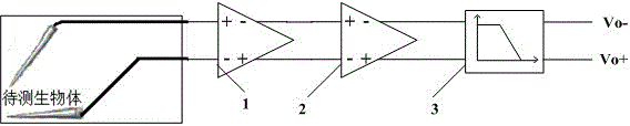
[0037] refer to figure 1 , a CMOS biomedical signal acquisition device with a differential capacitor network feedback structure, including a differential preamplifier 1, a differential variable gain amplifier 2 and a differential fourth-order switched capacitor filter 3; wherein, the forward output of the differential preamplifier 1 is connected to the differential The reverse input terminal of the variable gain amplifier 2 is connected, the negative output terminal of the differen...


PUM


Abstract

The invention discloses a CMOS (complementary metal-oxide semiconductor transistor) biomedical signal acquisition unit in a differential capacitance network feedback structure. The CMOS biomedical signal acquisition unit comprises a differential preamplifier, a differential variable gain amplifier and a differential four-order switch capacitance filter. A positive output end of the differential preamplifier is connected with a reverse input end of the differential variable gain amplifier, a reverse output end of the differential preamplifier is connected with a positive input end of the differential variable gain amplifier, a positive output end of the differential variable gain amplifier is connected with a positive input end of the differential four-order switch capacitance filter, and a reverse output end of the differential variable gain amplifier is connected with a reverse input end of the differential four-order switch capacitance filter. Creatively, the differential capacitance feedback network structure is adopted in the preamplifier in the field of biomedical signal acquisition, and common mode rejection ratio of the acquisition circuit is increased while capacitance of a capacitor is reduced.

Description

technical field [0001] The invention relates to the interdisciplinary technical fields of circuits and systems, microelectronics, integrated circuit design methodology and biomedical electronics, and in particular to a CMOS biomedical signal collector with a differential capacitance network feedback structure. Background technique [0002] my country is the country with the largest population in the world, which will inevitably lead to the largest demand for general medical services; moreover, the problem of population aging in my country is becoming more and more prominent, which has brought a heavy burden to my country's current medical system. [0003] On the other hand, with the acceleration of people's life rhythm, work pressure is increasing, and the number of people in a sub-health state is also increasing. Heart disease, high blood pressure, and diabetes have become the three major killers affecting people's health. Early diagnosis and timely treatment of sudden dise...

Claims


Application Information

Patent Timeline
Patent Type & Authority Patents(China)
IPC IPC(8): H03H11/02
Inventor 吴朝晖梁凯李斌
Owner SOUTH CHINA UNIV OF TECH
Why Eureka
Try Eureka