Device for measuring shearing force of metal part

A measuring device and shearing force technology, applied in the direction of measuring device, using stable shearing force to test material strength, using force balance force measurement, etc., can solve the problem of not fully reflecting the real situation and strength, calibration and solution Problems such as complicated process and complicated testing and testing equipment can achieve the effect of high testing efficiency, high measurement response speed and precision, and simple structure

Inactive Publication Date: 2013-01-02
SHAANXI UNIV OF SCI & TECH
View PDF9 Cites 8 Cited by
  • Summary
  • Abstract
  • Description
  • Claims
  • Application Information

AI Technical Summary

Problems solved by technology

[0002] At present, the main application of measuring shear force is on bearing products, and the detection principle of its testing equipment is mainly to use the strain measurement method; specifically, a dynamic load is applied to the metal strain gauge attached in the middle of the testing bearing product, so that it is subjected to strain measurement. The local stress is obtained, and the strain-stress curve is fitted according to the local stress data, and the stress is calculated inversely on the curve, and then the shear force of the support is calculated; The force-bearing area and friction coefficient are calculated by using the support shear force calculation formula; the principle application is reflected in: 201010160564.3 patent number "one-way support shear force measurement device and measurement method", 200810186045.7 patent number "microcomputer control Electro-hydraulic servo multi-functional compression-shear testing machine: Patent No. 200710044755.1, which is used to detect product shear stress wrinkling, introduces "metal sheet shear stress wrinkling test method and test device, etc. The disadvantage is that the calibration and solution process of shear force is complicated and difficult to detect. The test equipment is complex, bulky, high cost, and low detection efficiency; in engineering production, high efficiency, direct reading, simple and convenient, accurate measurement accuracy, large measuring range, and batch inspection testing equipment suitable for mass production are often required in engineering production;
[0003] For example, the AC contactors of high and low voltage electrical appliances, the electromagnetic tripping parts of low voltage circuit breakers, contacts, brackets and other welded parts are tested for firm welding. Ultrasonic nondestructive testing is usually used to detect a fusion welding area on the horizontal plane, and the welding combination in the vertical direction The depth is not reflected, and cannot fully reflect the real situation and strength of the welding. Currently, destructive peeling is used to test and verify the depth of the welding joint and determine the firmness. With the development of the industrial product economy, more products are required to improve the grade and quality. Its carrying capacity, machinery or service life put forward higher requirements, and it has been promoted to a high-end or quality-trusted product brand. Many companies have invested in the research and development of testing equipment suitable for mass production and batch inspection.

Method used


Image

  • Device for measuring shearing force of metal part
  • Device for measuring shearing force of metal part
  • Device for measuring shearing force of metal part

Examples


Embodiment Construction

[0012] The present invention will be described in further detail below in conjunction with the accompanying drawings.

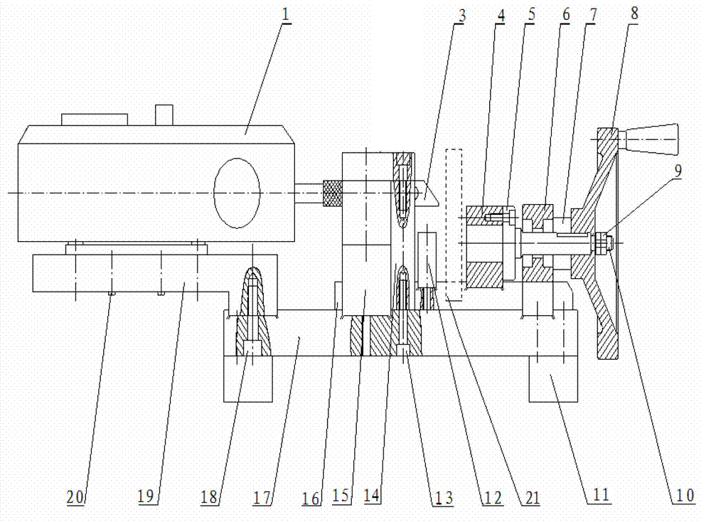
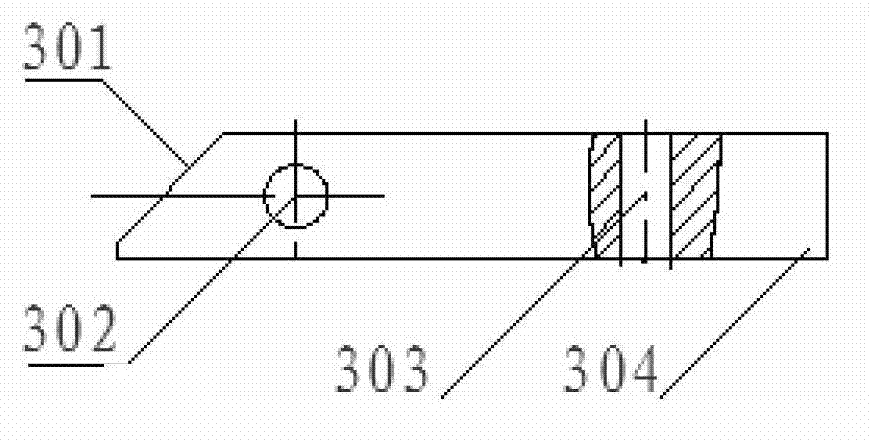
[0013] Such as figure 1 As shown, a metal piece shear force measurement device includes a large base plate 17, the top of the large base plate 17 is connected to the side support plate 19 through the first hexagonal socket screw 18, and the dynamometer 1 is fixed on the side support plate 19 through the small screw 20. , the shaft end of the dynamometer 1 is connected to one end of the working block 3 . The structure of work block 3 is as follows figure 2 As shown, one end is directly connected to the shaft end of the dynamometer 1 at a straight angle, and the other end has an oblique shear surface 301 and faces one end of the module 21 to be tested. There are horizontal holes 302 and vertical holes 303 on the working block 3, The horizontal hole 302 is connected to the clamping block 14, and the clamping block 14 is fixed to the slide plate 16 by the seco...


PUM


Abstract

The invention provides a device for measuring a shearing force of a metal part. The device comprises a large bottom plate, wherein a side support plate is connected above the large bottom plate and equipped with a forcemeter; a shaft end of the forcemeter is connected with one end of a working block and the other end of the working block is equipped with a bevel shearing surface and faces to one end of a module to be measured; the working block is fixedly connected with a clamping block and a working support block on a sliding plate which is arranged on a sliding chute on the large bottom plate; the other end of the module to be measured faces to a screw end of a revolving axle; a pushing block, a flange, a revolving support block, a locating block and a rocker arm are sleeved on the revolving axle in sequence from the screw end to a threaded end; the pushing block is fixed by the flange and the bottom of the pushing block is mounted on the sliding plate; and the bottom of the revolving support block is mounted on the sliding plate. The device of the invention has the advantages that the rigidity is good, the bearing is large, the processing is convenient, the cost is saved, the operation is simple, the measuring response speed and accuracy is high, the measurement is accurate, the running is stable and reliable, the direct reading can be achieved, the measuring efficiency is high, and the gap of measuring the shearing force in the weld assembly quality inspection of high-low voltage electrical equipment is filled.

Description

technical field [0001] The invention relates to the technical field of welding control of electric metal parts of high and low voltage electrical appliances, in particular to a metal part shear force measuring device. Background technique [0002] At present, the main application of measuring shear force is on bearing products, and the detection principle of its testing equipment is mainly to use the strain measurement method; specifically, a dynamic load is applied to the metal strain gauge attached in the middle of the testing bearing product, so that it is subjected to strain measurement. The local stress is obtained, and the strain-stress curve is fitted according to the local stress data, and the stress is calculated inversely on the curve, and then the shear force of the support is calculated; The force-bearing area and friction coefficient are calculated by using the support shear force calculation formula; the principle application is reflected in: 201010160564.3 pat...

Claims


Application Information

Patent Timeline
Patent Type & Authority Applications(China)
IPC IPC(8): G01L1/08G01N3/06G01N3/24
Inventor 郑梅黄和平
Owner SHAANXI UNIV OF SCI & TECH
Why Eureka
Try Eureka