
Lead provided with active solder coating and using method thereof

An active solder and coating technology, applied in semiconductor devices, climate sustainability, photovoltaic power generation, etc., can solve problems affecting the overall production capacity of batteries, time-consuming and complicated steps, and unfavorable solderability

Active Publication Date: 2013-01-02
NAT PINGTUNG UNIV OF SCI & TECH
View PDF4 Cites 0 Cited by
  • Summary
  • Abstract
  • Description
  • Claims
  • Application Information

AI Technical Summary

Problems solved by technology

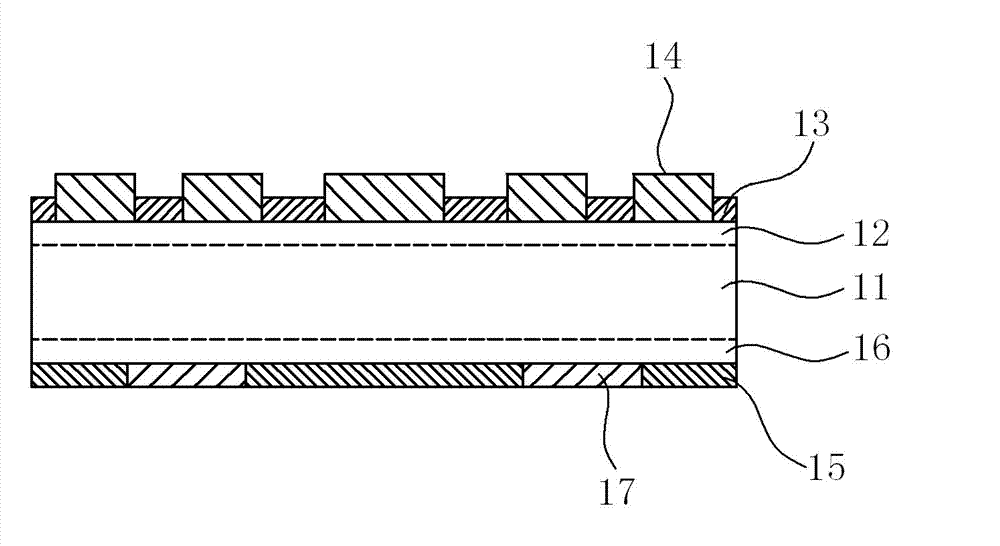
[0005] However, the actual manufacture of existing solar cell modules still has the following problems. For example, the conductive pastes such as silver, aluminum, and silver-aluminum are used to connect the front electrode layer 14, the back electrode layer 15, and the wires 17. Electrodes and wires, but the material cost of the silver, aluminum and silver-aluminum conductive paste is quite high, accounting for about 10 to 20% of the entire module manufacturing cost
Furthermore, these conductive pastes contain a certain proportion of metal powder, glass powder and organic media, such as Japanese Kokai Patent Publication No. 2001-127317 and No. 2004-146521 and Taiwan Patent Announcement No. I339400 filed by DuPont of Taiwan. , the conductive paste contains glass particles that reduce electrical conductivity and are not conducive to solderability; and it also contains organic solvents and other components, so it will cause pollution to the solar chip after sintering, so it must be cleaned specially
Furthermore, the use of conductive paste to make wires must be sintered at a high temperature of about 450 to 850°C, but this high temperature condition may cause deterioration or failure of other material layers, which will seriously affect the yield of the battery.
Based on the demand for precise control of the above-mentioned high-temperature sintering conditions, the high-temperature sintering step is relatively time-consuming and complicated, and will affect the overall production capacity of the battery produced per unit time

Method used


Image

  • Lead provided with active solder coating and using method thereof
  • Lead provided with active solder coating and using method thereof
  • Lead provided with active solder coating and using method thereof

Examples


Embodiment Construction

[0026] In order to make the above and other objects, features and advantages of the present invention more comprehensible, preferred embodiments of the present invention will be exemplified below in detail together with the attached drawings. Furthermore, the directional terms mentioned in the present invention, such as "up", "down", "front", "rear", "left", "right", "inside", "outside" or "side", etc., It is only for orientation with reference to the attached drawings. Therefore, the directional terms used are used to illustrate and understand the present invention, but not to limit the present invention.

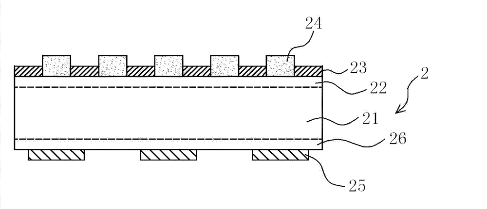
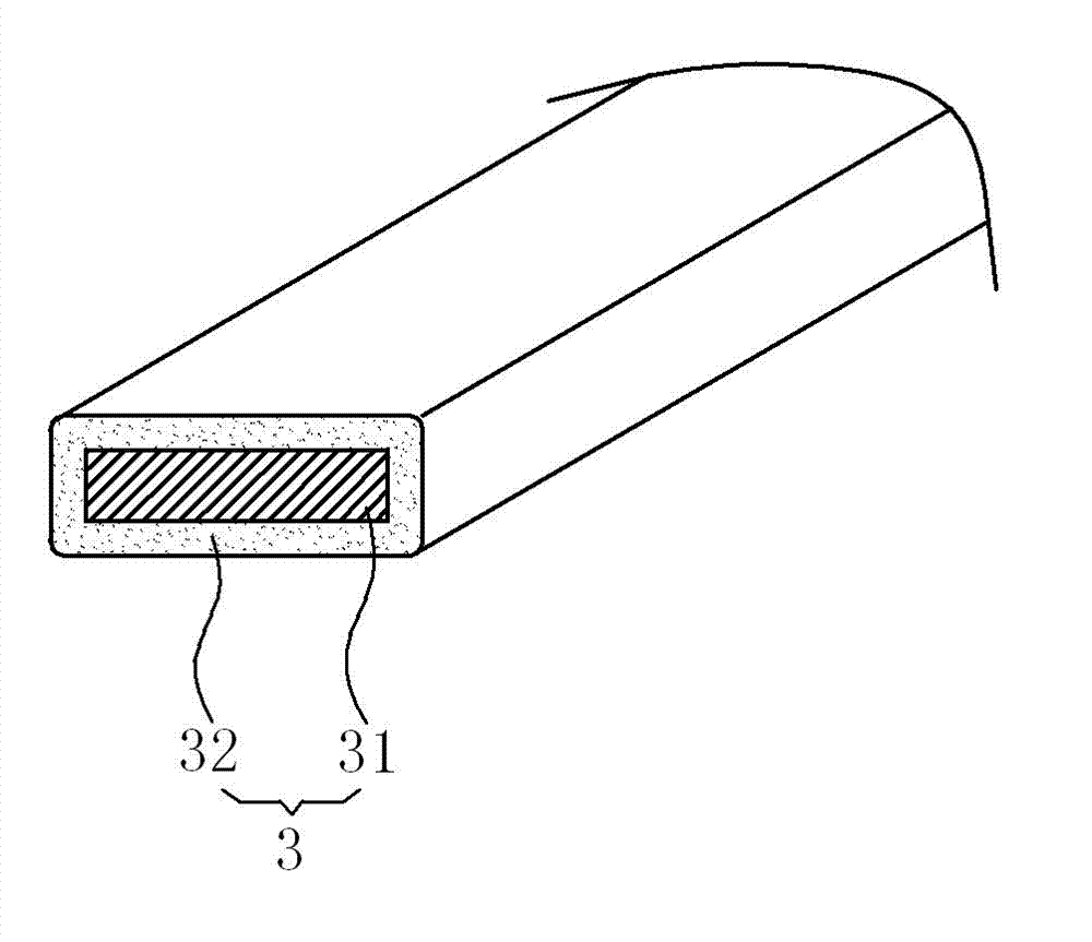
[0027] Please refer to attached Figure 2A to attach Figure 2D As shown, it discloses a schematic flow chart of a method for using a wire with an active solder coating according to a preferred embodiment of the present invention, wherein the method mainly includes the following steps: providing a substrate 2; providing a wire 3 having a wire 31 and An active solder coa...


PUM


Abstract

The invention provides a lead provided with an active solder coating and a using method thereof. The method includes steps of providing a substrate; providing a lead provided with a wire and the active solder coating coated on the wire. The active solder coating coated on the wire includes at least one soldering tin alloy mixed with less than 6 percents of at least one active component by weight and 0.01 percent to 2 percents of at least one rare earth element (Re) by weight. The method also includes steps of pre-heating the lead and the substrate at a temperature lower than 450 DEG C; and disposing the pre-heated lead on the pre-heated substrate, thereby making the active solder coating contact, melt and weld on the pre-heated substrate; and cooling and solidifying the active solder of the active solder coating of the lead and forming a circuit pattern through the lead.

Description

technical field [0001] The present invention relates to a solar battery electrode and a manufacturing method thereof, in particular to a wire with an active solder coating and a using method thereof. Background technique [0002] In recent years, due to the gradual shortage of fossil fuels, the development of various renewable alternative energy sources (such as solar cells, fuel cells, and wind power) has gradually attracted attention, among which solar power generation has attracted the most attention from all walks of life. [0003] Please refer to the attached figure 1 As shown, it discloses a cross-sectional view of an existing solar cell assembly, wherein when making this existing solar cell assembly, a p-type silicon semiconductor substrate 11 is firstly provided, and after the surface is roughened by acid etching, then phosphorus or similar The substance forms an n-type diffusion layer 12 of reverse conductivity type on the light-receiving surface side of the p-type...

Claims


Application Information

Patent Timeline
IPC IPC(8): H01L31/18H01L31/0224
CPCY02E10/50Y02P70/50
Inventor 曹龙泉
Owner NAT PINGTUNG UNIV OF SCI & TECH
Learn More