Reactive power control method and circuit of single-phase photovoltaic inverter

A photovoltaic inverter and inverter circuit technology, applied in photovoltaic power generation, reactive power compensation, reactive power adjustment/elimination/compensation, etc., can solve large switching losses, reduce inverter efficiency, and unfavorable reactive power control And other issues

Active Publication Date: 2013-01-02
BEIJING KINGLONG NEW ENERGY TECH
View PDF5 Cites 25 Cited by
  • Summary
  • Abstract
  • Description
  • Claims
  • Application Information

AI Technical Summary

Problems solved by technology

[0032] On the one hand, the bipolar control method can solve the reactive power compensation control very well, but the defects of this technical solution are: the switching loss of the power switching device is large, the service life is short, especially the efficiency of the inverter is reduced;
[0033] from Figure 2C It can be seen that in the bipolar reactive power control method, in each given period of the bipolar triangular carrier Uc, the four power switch tubes T1, T2, T3, and T4 are turned on and off, and the power switch tubes work When the switching loss is large, the service life is short, which has a certain impact on the efficiency of the entire inverter
[0034] 2. General unipolar reactive power control method
[0043] Depend on Figure 3C It can be seen that the usual unipolar control method also has its own defects: it wil

Method used


Image

  • Reactive power control method and circuit of single-phase photovoltaic inverter
  • Reactive power control method and circuit of single-phase photovoltaic inverter
  • Reactive power control method and circuit of single-phase photovoltaic inverter

Examples


Embodiment Construction

[0122] The specific implementation manners of the present invention will be further described in detail below in conjunction with the accompanying drawings. It should be noted that the embodiment of the reactive power control method according to the present invention is merely an example, but the present invention is not limited to this specific embodiment.

[0123] The invention discloses a single-phase photovoltaic inverter reactive power control method, which is a high-efficiency and high-performance reactive power control method with a digital signal processor (DSP) as the core. The invention can effectively use the sun to generate electricity, and at the same time adapt to new grid-connected requirements, can realize reactive power control, and reduce harmonic pollution to the grid.

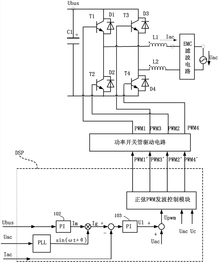
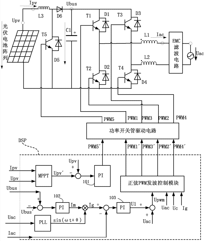
[0124] Such as Figure 1B The system structure diagram shown is a schematic diagram of the system structure of the reactive power control circuit of the single-phase photovoltaic inverter o...


PUM


Abstract

The invention discloses a reactive power control circuit of a single-phase photovoltaic inverter. The reactive power control circuit comprises a bus voltage supporting capacitor, a single-phase full-bridge inversion circuit, a filtering inductor, an EMC (Electro Magnetic Compatibility) filtering circuit, a sampling circuit, a power switch pipe driving circuit and a DSP (Digital Signal Processor), wherein the DSP consists of a PLL (Phase Locked Loop) control module, a voltage outer ring PI control module, a current inner ring PI feedforward control module and a sinusoidal PWM (Pulse-Width Modulation) wave sending control module, and an input signal of the sinusoidal PWM wave sending control module of the DSP further includes a current inner ring current given amount Ig. The invention further provides a reactive power control method of the single-phase photovoltaic inverter. The method not only can be used for judging whether the voltage Uac of a power grid is larger than zero, and comparing the absolute value of a PWM wave sending control input modulation wave Upwm with a given triangular carrier wave Uc, but also can be used for judging whether the given current inner ring current amount Ig is larger than zero. Not only can the conduction loss of a power switching tube be reduced, and the conversion efficiency of the inverter is improved, but also the current waveform can be continuous, an output harmonic wave is reduced, and the pollution on a harmonic wave of a power grid is reduced.

Description

technical field [0001] The present invention relates to the field of photovoltaic new energy, in particular to a single-phase photovoltaic inverter reactive power control method and circuit, which can be applied to single-phase photovoltaic inverter reactive power control of any power level, and can also be applied to single-phase circuit Static var compensation device. Background technique [0002] As the proportion of photovoltaic power generation in the power grid distribution system is increasing, the harmonic pollution of photovoltaic power generation to the power grid is also increasing, which also affects the power quality of the power grid; and in large power distribution systems, other users Electrical equipment will inevitably cause harmonic pollution to the grid. For these harmonic pollution, reactive power compensation can solve the harmonic pollution of part of the power grid very well. Compared with the photovoltaic inverter system without reactive power comp...

Claims


Application Information

Patent Timeline
IPC IPC(8): H02J3/18H02J3/01H02M7/5387
CPCY02E10/563Y02E40/30Y02E10/56Y02E40/40
Inventor 崔大龙郭海亚邢波
Owner BEIJING KINGLONG NEW ENERGY TECH
Why Eureka
Try Eureka