
Acoustic frequency detector and acoustic frequency detecting system with multi-mode coupler

A detection system and detector technology, used in the measurement of ultrasonic/sonic/infrasonic waves, instruments, measuring devices, etc., can solve problems such as phase errors, and achieve the effect of ensuring accuracy, easy rapid mass production, and easy long-distance transmission

Active Publication Date: 2013-01-16
HUAZHONG UNIV OF SCI & TECH
View PDF2 Cites 3 Cited by
  • Summary
  • Abstract
  • Description
  • Claims
  • Application Information

AI Technical Summary

Problems solved by technology

The measurement sensitivity of this method can reach 5.6mV / Pa, and the measurement frequency range is 10kHz-1mHz; the frequency detection range of the fiber optic interferometer acoustic sensor can reach 40Hz-400kHz, and the sensitivity is high, but it is easy to cause phase error
For example, in 2008, Wu Dongfang and others from Fudan University did a series of research on the Sagnac interferometric fiber optic microphone. The experimental results showed that the bandwidth was 10Hz-200kHz, and the signal-to-noise ratio was as high as 60dB; the fiber grating acoustic sensor has high sensitivity and stability. Good, but only good for detecting high frequency acoustic signals above 10kHz

Method used


Image

  • Acoustic frequency detector and acoustic frequency detecting system with multi-mode coupler
  • Acoustic frequency detector and acoustic frequency detecting system with multi-mode coupler
  • Acoustic frequency detector and acoustic frequency detecting system with multi-mode coupler

Examples


Embodiment Construction

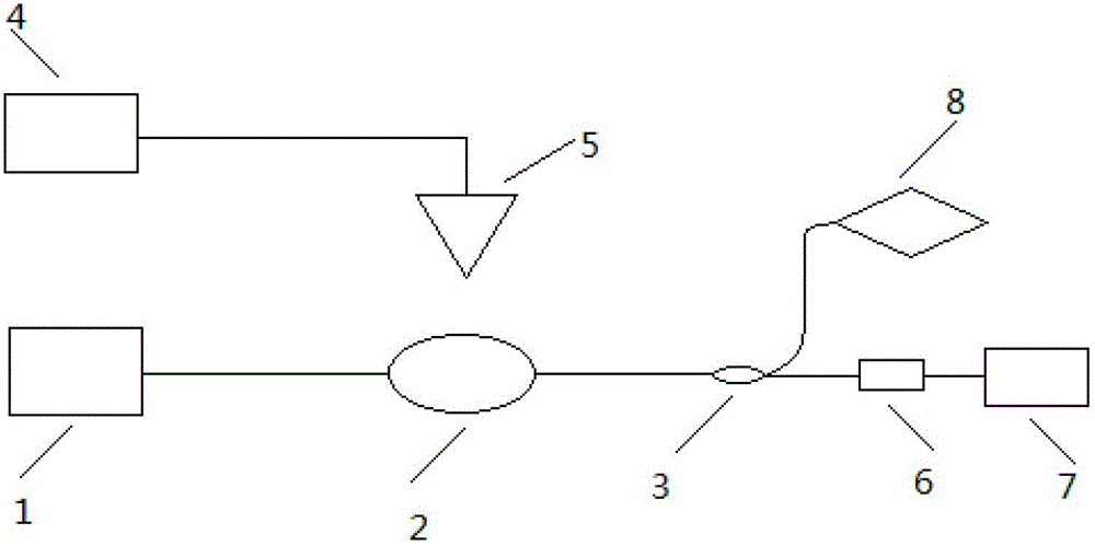
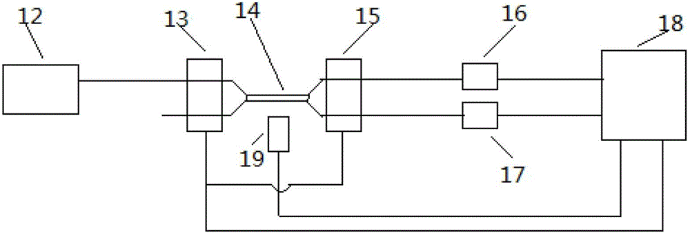
[0019] figure 1 The structure diagram of the multi-mode coupler acoustic frequency detection system is given. The audio signal generator 4 of the virtual instrument software sends out a specific single-frequency acoustic signal through the connection with the speaker 5 . The wide-spectrum light source 1 is connected to the acoustic frequency detector 2 through a common single-mode optical fiber. When an acoustic signal of a specific frequency acts on the acoustic frequency detector, the acoustic frequency detector is caused to resonate, and the acoustic frequency signal is converted into a change in the optical signal. The output end of the acoustic wave frequency detector is connected to the 1×2 fiber optic coupler 3, and one output end of the 1×2 fiber optic coupler 3 is connected to the optical oscilloscope 8, which dynamically scans the time-domain fluctuation of the optical signal passing through the acoustic wave frequency detector in real time. The other output end of t...


PUM


Abstract

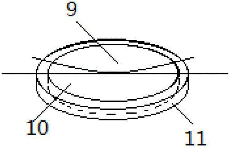
The invention relates to an acoustic frequency detector and an acoustic frequency detecting system with a multi-mode coupler. The acoustic frequency detector comprises a multi-mode optical fiber coupler, an aluminum film and a metal block, the diameter of the circular aluminum film ranges from 30mm to 40mm, the thickness of the circular aluminum film ranges from 2.5 micrometers to 3.5 micrometers, the periphery of the circular aluminum film is flatly adhered on the metal block, two ends of the multi-mode optical fiber coupler are fixed, a middle coupling region of the multi-mode optical fiber coupler naturally droops to be in contact with the aluminum film, and the length of the middle coupling region ranges from 5mm to 10mm. The acoustic frequency detecting system with the multi-mode coupler comprises the acoustic frequency detector, an acoustic frequency signal generator, a loudspeaker, a wide-spectrum light source, a 1X2 optical fiber coupler, a high-speed photovoltaic conversion module and a frequency spectrum analyzer. Compared with the traditional acoustic frequency detector and the traditional acoustic frequency detecting system which are implemented in a capacitance detecting method, the acoustic frequency detector and the acoustic frequency detecting system have the advantages of high interference resistance and easiness in long-distance transmission owing to an optical fiber acoustic sensing mode.

Description

technical field [0001] The invention relates to a sound wave frequency detector and a multimode coupler sound wave frequency detection system. Background technique [0002] Accurate acoustic frequency detection is important in fiber optic communication and fiber optic sensing systems. [0003] The most commonly used means of sound wave frequency detection is to use a condenser microphone, which has two metal plates, one of which is coated with an electret film and grounded, and the other plate is connected to the gate of the field effect transistor. There is a diode connected to the source. When subjected to vibration or friction by air flow, the distance between the two plates changes due to the vibration, that is, the capacitance changes, but the electricity does not change, which will cause a change in voltage. The magnitude of the voltage change reflects the strength of the external sound pressure. The frequency of this voltage change reflects the frequency of the outs...

Claims


Application Information

Patent Timeline
Patent Type & Authority Applications(China)
IPC IPC(8): G01H9/00
Inventor 鲁平王顺刘德明
Owner HUAZHONG UNIV OF SCI & TECH
Learn More