

Cam-driven oscillating mirror mechanism
A cam mechanism and cam technology, applied in the direction of optical components, optics, instruments, etc., can solve the problem of high rotation accuracy and dynamic performance requirements of torque motors, difficulty in overcoming the friction and influence of return springs, and affecting the accuracy of yaw angle adjustment, etc. problem, to achieve the effect of simple structure, improved precision and guaranteed stability
Inactive Publication Date: 2013-01-16
TONGJI UNIV
View PDF6 Cites 26 Cited by
- Summary
- Abstract
- Description
- Claims
- Application Information
AI Technical Summary
Problems solved by technology
[0003] In the prior technology (Sun Jianfeng and other patents, application number: 200410024986.2, application date October 2004 "High-precision dynamic and static measurement device for inter-satellite laser communication terminals"), the torque motor is used to directly couple the rotating shaft to realize the deflection of the optical element, thereby Angle adjustment is realized, but the mechanical system has high requirements on the rotation accuracy and dynamic performance of the torque motor, and the mechanical error is relatively large
[0004] In the prior technology (Patent by Li Anhu, application number: 200510026553.5, application date: June 2005 "Double optical wedge beam deflection mechanism"), a linear motor direct jacking drive method is proposed, which belongs to the variable load system during motion, not only It is difficult to guarantee the control accuracy, and it is difficult to overcome the friction and influence generated by the return spring and the ejector rod during the movement
[0005] In the prior technology (Patent of Li Anhu et al., application number: 201010588924.X, application date December 2010 "Scanning Device for Swinging Optical Wedge"), the yaw movement of the optical wedge is realized through the kinematic coupling of three mechanical modules, but due to Both the first module and the third module adopt the sliding guide rail scheme, which is realized by sliding the slider on its guide rail. Therefore, the accumulation of errors generated by the two-stage sliding guide rails affects the accuracy of the yaw angle adjustment. At the same time, the second module There is also a movement gap in the use of joint bearings, which affects the accuracy of the system
Method used
View moreImage
Smart ImageViewing Examples

Examples
specific example
[0072] Concrete example: take r 0 =30, a=100, b=60, the maximum swing angle of the pendulum φ max =10°, push motion angle ∠1=180°, return motion angle ∠2=180°; the movement law of the pendulum: both the push stroke and the return stroke are quadratic polynomial motion laws. According to the above parameters and formula (1) ~ formula (5), etc., draw the figure through MATLAB programming and finally get the following Figure 13 The cam profile curve shown.
Login to View More PUM
 Abstract
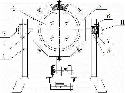
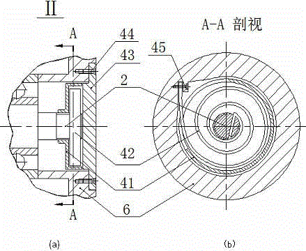
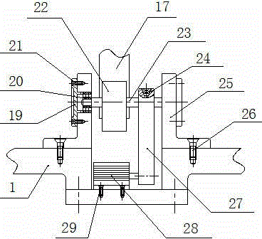
The invention relates to a cam-driven oscillating mirror mechanism which comprises a mirror frame and rotary half shaft assembly, a spring close connection device, a deflection cam mechanism, a motor and transmission portion, an oscillating mirror supporting structure and a base. The mirror frame and rotary half shaft assembly comprises an oscillating mirror, a rotary half shaft, a mirror frame, a first rolling bearing, a first bearing end cover, a first sunk screw and an angle encoder. The spring close connection device comprises a spring shield, a planar scroll spring and an outer cover, and the deflection cam mechanism comprises a deflection plate, a cam, a cam shaft and a cam holder. The motor and transmission portion consists of a belt pulley, a V-belt and a motor. The cam-driven oscillating mirror mechanism has the advantages of simple structure, low noise, stability in transmission, low cost, capability of buffering and absorbing vibration, and the like.
Description
technical field [0001] The invention relates to a swinging mirror mechanism driven by a cam, which can be used for precise scanning, tracking and alignment of light beams in the field of precision engineering. Background technique [0002] The oscillating mirror mechanism has a wide range of applications in dynamic optical tracking, which can accurately realize the alignment of the optical path, the tracking of the measured object, and the compensation and correction of the beam pointing error. Precise control of the yaw motion of the oscillating mirror is an important factor to improve the system accuracy. [0003] In the prior technology (Sun Jianfeng and other patents, application number: 200410024986.2, application date October 2004 "High-precision dynamic and static measurement device for inter-satellite laser communication terminals"), the torque motor is used to directly couple the rotating shaft to realize the deflection of the optical element, thereby Angle adjust...
Claims
Login to View More Application Information
Patent Timeline
 Patent Type & AuthorityApplications(China)
IPC IPC(8): G02B26/08
Inventor李安虎王伟丁烨高心健
OwnerTONGJI UNIV