Sintering molding process of electromagnetic coil of electrical equipment

A technology of sintering and forming electromagnetic coils, which is applied in the direction of coils, coil manufacturing, transformer/inductor coils/windings/connections, etc. It can solve problems such as increasing the size of winding or coil structures, increasing the thickness of insulating materials, and prolonging the production cycle. Achieve the effects of reducing the overall size, improving the electrical strength of the insulation, and improving the mechanical strength

Active Publication Date: 2016-05-04
尤大千
View PDF6 Cites 0 Cited by
  • Summary
  • Abstract
  • Description
  • Claims
  • Application Information

AI Technical Summary

Problems solved by technology

Therefore, the composite insulation using vacuum impregnation or casting process will inevitably lead to the third disadvantage, that is, the thickness of the insulating material has to be increased, and the structural size of the winding or coil must be increased.
Fourth, the production process is complicated, prolonging the production cycle
All of this means an increase in product cost

Method used


Image

  • Sintering molding process of electromagnetic coil of electrical equipment
  • Sintering molding process of electromagnetic coil of electrical equipment

Examples


Embodiment 1

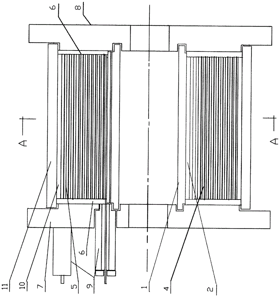
[0033] Prepare a capacitive additional winding for a single-phase compliant isolation transformer. The conductor is two layers of aluminum foil with a thickness of 0.03mm and a width of 400mm. The interlayer insulation is 2 * 0.025mm thick and 420mm wide polypropylene film. The end seal insulation is 1 * 0.03mm thick and 10mm wide polypropylene film tape. The lead wire is 0.03*20mm copper strip, the total thickness of the inner and outer main insulation layers is 1mm, the total thickness of the winding is 30mm, and the outer diameter is 350mm.

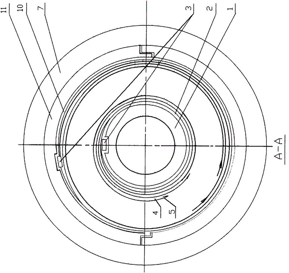
[0034] First, the upper end cap 8, the lower end cap 9 and the mold core 1 of the metal mold are fixed on the winding shaft of the wrapping machine, and the inner main insulating layer 2 and the outer metal conductor 4 of the welding lead 3 are wound on the metal mold core 1 , interlayer insulation layer 5, end seal insulation layer 6 and outer main insulation layer 7, adopt traditional winding or coil winding procedures and methods, a...


PUM


Abstract

The invention discloses an insulated winding or electromagnetic coil for electrical equipment and a sintering and forming process of the insulated winding or electromagnetic coil. The insulated winding or electromagnetic coil for the electrical equipment is a metal conductor for winding and welding a lead outside an inner main insulating layer; an interlayer insulating film is wound among various layers of the metal conductor; end-sealed insulating layers are wound at two ends of each layer of coil while the winding of the metal conductor and the interlayer insulation are realized simultaneously and sequentially realized; and an outer main insulating layer is wound outside the metal conductor of the winding or coil wound according to the specified turn numbers and layer numbers. The sintering and forming process of the insulated winding or electromagnetic coil is mainly characterized in that the winding or coil is wound by an inner main insulating layer, an external winding welding lead metal conductor, an interlayer insulating film, the end-sealed insulating layers and the outer main insulating layer on a die core of a metal die; a reinforced insulating layer is packed at the welded part of a lead or joint and a tap; the metal die in which the winding or coil is arranged is filled into a vacuum pressure sintering furnace, so that the insulating material and the metal conductor are bonded and integrally formed; and the electrical strength and the heat radiating effect of the insulating material are improved, so that the size is reduced, the process flow is simplified and the cost is reduced.

Description

technical field [0001] The invention relates to insulating windings and electromagnetic coils of electrical equipment, in particular to a sintering molding process for electromagnetic coils of electrical equipment. Background technique [0002] At present, the insulated windings and electromagnetic coils of general electrical equipment (including transformers, transformers, reactors, instruments and meters, and control appliances) use insulated conductors to wind single-layer or multi-layer coils on insulating cylinders or skeletons. Some of them are vacuumed and soaked in insulating oil after drying, some are vacuumed and soaked in insulating paint and then dried, and some are vacuumed and poured with epoxy resin. [0003] This structure of insulating windings and electromagnetic coils suffers from a number of disadvantages. First of all, its insulation is a composite of two materials. When the dielectric constant, dielectric strength (that is, the highest voltage that can...

Claims


Application Information

Patent Timeline
Patent Type & Authority Patents(China)
IPC IPC(8): H01F27/28H01F27/32H01F5/06H01F41/04
Inventor 尤大千
Owner 尤大千
Why Eureka
Try Eureka