Solar cell and manufacturing method thereof

A technology of solar cells and manufacturing methods, applied in the field of solar cells, can solve the problems of low photoelectric conversion efficiency of solar cells, and achieve the effects of reducing recombination, reducing electrical contact area, and reducing ohmic contact resistance

Active Publication Date: 2013-02-06
上饶捷泰新能源科技有限公司
View PDF5 Cites 12 Cited by
  • Summary
  • Abstract
  • Description
  • Claims
  • Application Information

AI Technical Summary

Problems solved by technology

[0012] However, in practical applications, it is found that the photoelectric conversion efficiency of conventional solar cells is low.

Method used


Image

  • Solar cell and manufacturing method thereof
  • Solar cell and manufacturing method thereof
  • Solar cell and manufacturing method thereof

Examples


Embodiment 1

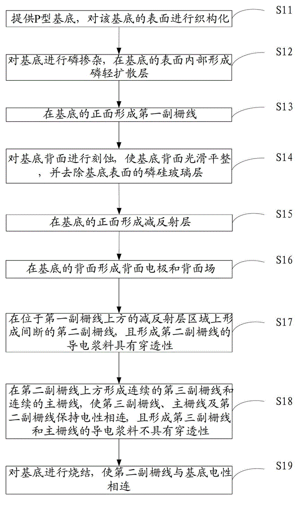
[0065] This embodiment provides a method for manufacturing a solar cell, such as figure 2 As shown, it is a flow chart of the manufacturing method of the solar cell provided by Embodiment 1 of the present invention, such as Figure 3-Figure 11 As shown, it is a perspective view of each step of the method, including:

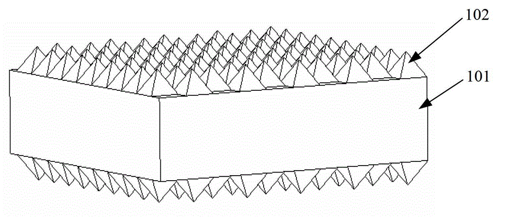
[0066] Step S11: providing a P-type substrate, and texturing the surface of the substrate.

[0067] Such as image 3 As shown, a P-type monocrystalline silicon wafer is provided as a substrate, most of the substrate is the body layer 101, and the substrate has a specification of 125mm×125mm, a resistivity of 1.5Ω·cm, and a thickness of 180μm; chemical etching is then used The substrate surface is textured by the method, and the pyramid structure 102 is finally formed. The chemical reagent used in the process is a sodium hydroxide solution with a temperature of 80°C and a mass percentage of 2.5%, and the corrosion time lasts for 25 minutes.

[0068] It should ...

Embodiment 2

[0137] This embodiment provides a method for manufacturing a solar cell, such as Figure 12 As shown, it is a flow chart of the manufacturing method of the solar cell provided by Embodiment 2 of the present invention, which specifically includes the following steps:

[0138] Step S21: providing an N-type substrate, and texturing the surface of the substrate.

[0139] An N-type monocrystalline silicon wafer is provided as the substrate, most of the substrate is the body layer 201, and the specification of the substrate is 156mm×156mm, the resistivity is 1.5Ω·cm, and the thickness is 180μm; The surface of the substrate is textured to finally form a pyramid structure 202. The chemical reagent used in the process is a sodium hydroxide solution with a temperature of 80°C and a mass percentage of 2.5%, and the corrosion time lasts for 25 minutes.

[0140] Step S22: Boron doping is performed on the substrate to form a boron light diffusion layer inside the surface of the substrate. ...


PUM


Abstract

The invention provides a solar cell and a manufacturing method thereof. The manufacturing method comprises the following steps of: providing a substrate, wherein the substrate comprises a body layer and a diffusion layer covering the front surface of the body layer; carrying out partial heavy doping on the diffusion layer to form a first secondary grid line; forming a refraction-reducing layer on the front surface of the substrate; forming a discontinuous second secondary grid line above the first secondary grid line; forming a continuous main grid line and a third secondary grid line above the second secondary grid line; and sintering the substrate. According to the solar cell and the manufacturing method thereof provided by the invention, the third secondary grid line does not contact the substrate, and the second secondary grid line and the substrate are in point contact, so that the compounding of current carriers on the surface of the substrate is reduce; in addition, the partial heavy doping is carried out on the diffusion layer to realize the partial heavy doping at a partial optical contact part of a front electrode and the substrate, so that ohmic contact resistance between the front electrode of the solar cell and the substrate is reduced as compared with that in the prior art, and the photoelectric conversion efficiency of the solar cell is improved.

Description

technical field [0001] The invention relates to the technical field of solar cells, and more specifically, to a solar cell and a manufacturing method thereof. Background technique [0002] A solar cell, also known as a photovoltaic cell, is a semiconductor device that converts the sun's light energy directly into electrical energy. Because it is a green product, does not cause environmental pollution, and is a renewable resource, solar cells are a new energy source with broad development prospects in today's energy shortage situation. [0003] One of the most important criteria to measure the electrical performance of a solar cell is its photoelectric conversion efficiency. The higher the photoelectric conversion efficiency of a solar cell, the stronger its ability to convert light energy into electrical energy. [0004] The basic structure of the most common crystalline silicon solar cells, such as figure 1 As shown, it is the basic structure of a common solar cell in the...

Claims


Application Information

Patent Timeline
Patent Type & Authority Applications(China)
IPC IPC(8): H01L31/18H01L31/0224
CPCY02P70/50
Inventor 金井升黄纪德王单单许佳平蒋方丹
Owner 上饶捷泰新能源科技有限公司
Why Eureka
Try Eureka