
Sewage treatment system and method for natural gas purifying factory in H2S-containing gas field

A sewage treatment method and sewage pretreatment technology, applied in water/sewage multi-stage treatment, water/sludge/sewage treatment, gaseous effluent wastewater treatment, etc., can solve the problems of difficult biochemical treatment, increased pollution load, and frequent regeneration and other issues, to achieve the effect of reducing maintenance and management workload, reducing the toxicity of harmful substances, and reducing the concentration of organic matter

Active Publication Date: 2014-03-12
BC P INC CHINA NAT PETROLEUM CORP +1
View PDF6 Cites 0 Cited by
  • Summary
  • Abstract
  • Description
  • Claims
  • Application Information

AI Technical Summary

Problems solved by technology

[0004] 1.H 2 S will cause severe corrosion of wellhead equipment and raw gas pipelines, causing a large amount of corrosion products to enter the purification plant with the raw gas
[0005] 2. Gas field contains H 2 When S is high, it is often necessary to introduce desulfurization solutions such as sulfolane and methyldiethanolamine and dehydrating agents such as triethylene glycol. Once the desulfurization and dehydration solutions are lost, the COD value of sewage will increase exponentially, and due to the stable molecular structure of sulfolane, it is difficult to degrade. Not easy to biochemically treat
[0006] 3. The solution pollutes the filter. When the filter is backwashed, a large amount of organic solvent will enter the sewage treatment device, which will greatly increase the pollution load in a short time.
[0011] The activated carbon adsorption method has high requirements for pretreatment, high cost of activated carbon, easy loss of particles, frequent regeneration, and high long-term operating costs

Method used


Image

  • Sewage treatment system and method for natural gas purifying factory in H2S-containing gas field

Examples


Embodiment Construction

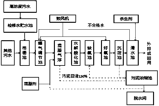
[0031] a H 2 The sewage treatment system of the S gas field natural gas purification plant, such as figure 1 As shown, it includes: maintenance water storage tank, grid tank, aeration adjustment tank, coagulation air flotation device, hydrolysis acidification tank, anoxic tank, aerobic tank, sedimentation tank and clean water tank connected in sequence; the clean water tank is also passed through The pipeline is connected to the aeration regulating tank, which is used to introduce unqualified water into the aeration regulating tank; the blower aerates the aeration regulating tank and the aerobic tank; The sedimentation tank is connected to collect sludge for thickening; the sludge thickening tank is further connected to the dehydration room. The present invention is also provided with sewage recycling equipment for reusing the treated sewage.

[0032] The present invention also provides a 2 The sewage treatment method of S gas field natural gas purification plant comprises ...


PUM

PropertyMeasurementUnit
surface areaaaaaaaaaaa

Abstract

The invention discloses a sewage treatment system and method for a natural gas purifying factory in H2S-containing gas field. By adopting a biological treatment process comprising pre-aeration, air floatation, hydrolytic acidification, anaerobic treatment, aerobic treatment, and precipitation, the quality of the treated water meets the primary standard of supreme permissible effluent concentration of the second category of hazardous in national integrated wastewater discharge standard. According to the invention, innovation is created based on anaerobism-aerobism of conventional purifying factory biochemical sewage treatment processes, and a sewage pretreatment step realized by hydrolytic acidification is added, thus water quality and quantity are effectively adjusted, the biodegradability of the sewage is greatly raised, and favorable conditions are created for posttreatment of the sewage; in the stage of subsequent treatment, the anaerobic-aerobic segment is changed into an aerobic-anaerobic segment, the sewage retention time is greatly reduced, the volume of treatment building is correspondingly reduced, thus the engineering investment is saved, and the workload of maintenance management is reduced.

Description

technical field [0001] The invention relates to a wastewater treatment technology, in particular to a 2 Treatment technology of sewage from natural gas purification plant in S gas field. Background technique [0002] With the increasing demand for natural gas at home and abroad, my country has intensified the development and utilization of natural gas. The sewage treatment technology level of natural gas purification plants will directly affect the selection of natural gas purification process methods and the speed of natural gas purification development. If the extracted raw natural gas contains H 2 S is relatively high, and it must be purified before it can be delivered to users. The purification of natural gas mainly adopts the desulfurization method of alcohol amines. The waste water generated during the purification and maintenance process is difficult to be discharged stably and meet the standards after conventional treatment due to large fluctuations in water qualit...

Claims


Application Information

Patent Timeline
Patent Type & Authority Patents(China)
IPC IPC(8): C02F9/14C02F103/18
Inventor 赵琼杨晓秋刘家洪胡益武李宇陈国平周宁肖芳张永红何蓉云曹亮杨洋郭俊
Owner BC P INC CHINA NAT PETROLEUM CORP
Learn More