
LED (Light-Emitting Diode) wafer modularized packaging process

A packaging process and LED chip technology, which is applied in lighting devices, lighting and heating equipment, electrical components, etc., can solve the problems of low LED chip packaging efficiency and high cost, and achieve high efficiency of packaging manufacturing process, increase production capacity, and increase speed. Effect

Inactive Publication Date: 2013-03-13
SHANGHAI DANGOO ELECTRONICS TARDING
View PDF4 Cites 6 Cited by
  • Summary
  • Abstract
  • Description
  • Claims
  • Application Information

AI Technical Summary

Problems solved by technology

[0004] The purpose of the present invention is to provide a LED chip modular packaging process to overcome the disadvantages of low LED chip packaging efficiency and high cost due to the existing manufacturing process in the LED chip packaging manufacturing process

Method used


Image

  • LED (Light-Emitting Diode) wafer modularized packaging process
  • LED (Light-Emitting Diode) wafer modularized packaging process

Examples


Embodiment Construction

[0011] The present invention will be further described below in conjunction with drawings and embodiments.

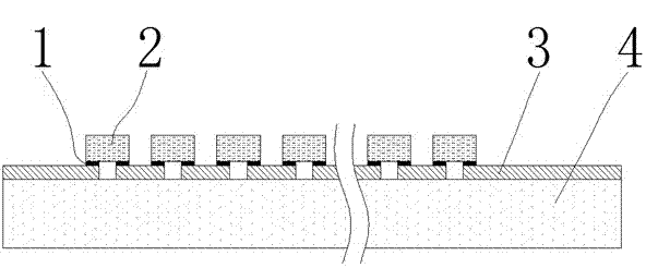
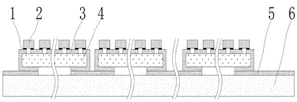
[0012] The specific steps of the LED chip modular packaging process of the present invention are as follows: first, a single or multiple LED chips with a front-mounted or flip-chip structure are connected in series and parallel to form an LED chip group, and then the LED chip group is pasted with an LED chip placement device. to the substrate or support.

[0013] After single or multiple LED chips are connected in series and parallel to form an LED chipset, the lead wires are metal wires, metal thin film wires or indium tin oxide (ITO) transparent wires. On the lead-out wire, the flip-chip LED chip is welded on the lead-out wire with eutectic solder joints.

[0014] The LED chip placement equipment is a solid crystal machine or a placement machine. The welding materials used for welding the LED chip and the lead wire are solder wire, solder paste and conductive adhesi...


PUM


Abstract

The invention relates to an LED (Light-Emitting Diode) wafer modularized packaging process which particularly comprises the following steps of: firstly connecting single or multiple LED chips in upright or reverse structures in series and in parallel to form an LED chipset; and then mounting the LED chipset to a substrate or a support frame by using LED chip mounting equipment. After the single or multiple LED chips are connected in series and in parallel to form the LED chipset, a metal wire and a metal film wire or a transparent indium tin oxide wire are adopted as outgoing wires, wherein the upright LED chips are welded on the outgoing wires by using gold wires and ball welding spots, and the reverse LED chips are welded on the outgoing wires by using eutectic welding spots; and the LED chip mounting equipment is a solid-phase crystallization machine or a chip mounting machine. The LED wafer modularized packaging process disclosed by the invention ensures that the packaging and manufacturing processes of the LED chips are more efficient; and compared with the traditional LED packaging mode, the LED wafer modularized packaging process disclosed by the invention adopts the simplest chip mounting manufacturing mode of a chip mounting resistor, thereby greatly increasing the speed of LED packaging and manufacturing, enhancing the productivity and reducing the cost.

Description

technical field [0001] The invention relates to an LED chip packaging process, in particular to a modular LED chip packaging process. Background technique [0002] LED is a light-emitting diode (LED, Lighting emitted diode), which is a solid-state light-emitting device that uses the PN junction to emit light under the action of an electric field. With the characteristics of high life / environmental protection / energy saving, it is a new green light source. LED technology is becoming more and more mature. At present, LEDs usually emit white light through blue chips to excite yellow-green phosphors, and then adjust the wavelength to produce white light. The efficiency of warm white light produced on a large scale in the market reaches 120 lm / W, surpassing most traditional LEDs. light source. Generally speaking, LED grows p-type layer, n-type layer and p-n junction light-emitting layer on sapphire substrate or silicon carbide substrate by MOCVD (Metal-organic Chemical Vapor...

Claims


Application Information

Patent Timeline
Patent Type & Authority Applications(China)
IPC IPC(8): H01L33/62H01L33/64
CPCH01L2924/0002F21K9/90H01L25/0753H01L2224/16
Inventor 瞿崧文国军严华锋
Owner SHANGHAI DANGOO ELECTRONICS TARDING
Learn More