Coke oven gas desulfurization equipment

A coke oven gas and desulfurization equipment technology, which is applied in combustible gas purification, combustible gas purification/transformation, petroleum industry, etc., can solve the problems of desulfurization efficiency reduction, achieve the effects of preventing ammonia loss, increasing spraying density, and increasing spraying volume

Inactive Publication Date: 2013-03-20
济南冶金化工设备有限公司
View PDF7 Cites 8 Cited by
  • Summary
  • Abstract
  • Description
  • Claims
  • Application Information

AI Technical Summary

Problems solved by technology

[0004] The purpose of the present invention is to overcome the deficiency that the ammonia in the gas is absorbed by the coke oven gas desulfurization equipment that adopts the direct type gas coole

Method used


Image

  • Coke oven gas desulfurization equipment
  • Coke oven gas desulfurization equipment

Examples


Embodiment 1

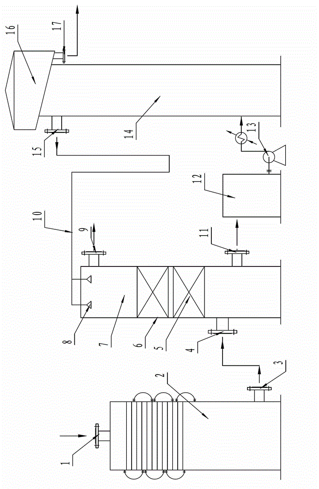
[0027]Embodiment 1, a kind of coke oven gas desulfurization equipment, its structure is: mainly comprises the gas indirect cooler connected together by pipeline, desulfurization tower, regeneration tower composition,

[0028] The connection relationship between each equipment is as follows: the gas outlet 3 of the gas indirect cooler 2 is connected to the gas inlet 4 of the desulfurization tower at the bottom of the desulfurization tower, the desulfurization liquid nozzle 8 is installed on the top of the desulfurization tower 6, and the purified gas outlet 9 is installed on the upper part of the desulfurization tower. The desulfurization waste liquid outlet 11 at the bottom is connected to the regeneration tower 14 through the solution circulation tank 12 and the pump 13. The upper part of the regeneration tower is provided with a regenerated desulfurization liquid outlet 15 and connected to the desulfurization tower through a desulfurization liquid circulation pipeline 10. The...

Embodiment 2

[0029] Embodiment 2, a kind of coke oven gas desulfurization equipment, its structure is: mainly comprises the gas indirect cooler connected together by pipeline, desulfurization tower, regeneration tower composition,

[0030] The connection relationship between each equipment is as follows: the gas outlet 3 of the gas indirect cooler 2 is connected to the gas inlet 4 of the desulfurization tower at the bottom of the desulfurization tower, the desulfurization liquid nozzle 8 is installed on the top of the desulfurization tower 6, and the purified gas outlet 9 is installed on the upper part of the desulfurization tower. The desulfurization waste liquid outlet 11 at the bottom is connected to the regeneration tower 14 through the solution circulation tank 12 and the pump 13. The upper part of the regeneration tower is provided with a regenerated desulfurization liquid outlet 15 and connected to the desulfurization tower through a desulfurization liquid circulation pipeline 10. Th...


PUM


Abstract

The invention discloses coke oven gas desulfurization equipment which belongs to equipment for removing sulfuretted hydrogen from ammonia and sulfuretted hydrogen-containing gases, and in particular relates to equipment for removing the sulfuretted hydrogen from coke oven gases. The coke oven gas desulfurization equipment has a structure that the coke oven gas desulfurization equipment mainly comprises a coal gas indirect cooler, a desulfurizing tower and a regenerating tower which are connected together through pipelines, the connection relationship of the devices is that a coal gas outlet of the coal gas indirect cooler is connected with a coal gas inlet on the bottom of the desulfurizing tower, a desulfurizing liquid nozzle is arranged on the top of the desulfurizing tower, a purified coal gas outlet is formed on the upper part of the desulfurizing tower, a desulfurizing liquid outlet on the bottom of the desulfurizing tower is connected with the regenerating tower through a solution circulating tank and a pump, a regeneration desulfurizing liquid outlet is formed on the upper part of the regenerating tower and is connected with the desulfurizing tower through a desulfurizing liquid circulating pipeline, a tower cover which contains a sulfur and foam separation device is arranged on the top of the regenerating tower, and a sulfur foam outlet is formed on the bottom of the tower cover. The coal gas indirect cooler is adopted to cool coal gas to 20-22 DEG C before desulfurization, the structure of the desulfurizing tower is improved, and the desulfurizing efficiency is increased.

Description

technical field [0001] The invention belongs to equipment for removing hydrogen sulfide from gas containing ammonia and hydrogen sulfide, in particular to equipment for removing hydrogen sulfide from coke oven gas. Background technique [0002] One of the traditional technologies for removing hydrogen sulfide from coke oven gas is the wet oxidation desulfurization technology using ammonia as an alkali source. The mass concentration of ammonia in coke oven gas is only 5-7g / m 3 , while the mass concentration of hydrogen sulfide is mostly in the range of 5-10g / m 3 . Due to the low mass concentration of ammonia, the desulfurization efficiency is reduced, generally only 92-95%. The hydrogen sulfide content in the gas after removal is generally 250-400mg / m 3 . In the "Coking Chemical Industry Pollutant Discharge Standard" (GB16171-2012), which came into effect on October 1, 2012, the emission concentration limit of air pollutants from existing enterprises stipulates that the ...

Claims


Application Information

Patent Timeline
IPC IPC(8): C10K1/00C10K1/12
Inventor 王登富姜爱国季广祥温燕明汤志刚康春清陈善龙孙兆俊李桂花
Owner 济南冶金化工设备有限公司
Why Eureka
Try Eureka